

You are using an out of date browser. It may not display this or other websites correctly.
You should upgrade or use an alternative browser.
You should upgrade or use an alternative browser.
Trouble shooting silicon rectifier diodes in power supply.
- Thread starter HowardK
- Start date

Al Casey
Active Member
There may be an error in the diagram; either it shows
the bridge and the two isolation diodes suggested by @gadget73, or two rectifier bridges in parallel; in some Grommes amplifiers, you’ll find tube rectifiers connected in parallel—were they trying to achieve the same result with silicon diodes?
the bridge and the two isolation diodes suggested by @gadget73, or two rectifier bridges in parallel; in some Grommes amplifiers, you’ll find tube rectifiers connected in parallel—were they trying to achieve the same result with silicon diodes?

Thanks! For sure, the problem lies in the power supply.I hooked up my black box and set the wall voltage at 106 just for peace of mind. But they still went to 425.
No tubes el84 plate right side 425 left 411.
Just preamp driver tubes right 423 left 383
Yes, that doesn't make sense, since a full-wave, four-diode UF4007 bridge rectifier is more than adequate for this SE amp.I wonder why he changed the diodes to uf4007 from what's in the first addition like mine which I don't know what's in there.
Last edited:
Al Casey
Active Member
The heater supply is referenced to a dc voltage instead of the ground.What are the other diodes for on the heater center tap? The voltage on them kind of swing a volt to a volt in a half except the center one was sready.
Those are 1N4762A Zener diodes. My guess is that the string is used to regulate the raised heater voltage.What are the other diodes for on the heater center tap? The voltage on them kind of swing a volt to a volt in a half except the center one was sready.

whoaru99
Epic Member
UF is a fast switching diode, generally intended for high frequency switching type applications. Some assert there is an improvment in PS noise using them instead of "slow" diodes like 1N.I wonder why he changed the diodes to uf4007 from what's in the first addition like mine which I don't know what's in there.
Again though, they still serve the same basic function if they're working as diodes.

You know, this could work. There would be a lot fewer parts to deal with.
Just an idea.

whoaru99
Epic Member
You know, this could work. There would be a lot fewer parts to deal with.
Just an idea.
A lot would have to change to do that, and the circuit as originally laid out should work despite the unconventional appearance,
Well, it ain't working now.A lot would have to change to do that, and the circuit as originally laid out should work despite the unconventional appearance,

whoaru99
Epic Member
It shouldn't have to be redesigned to fix it was the point.Well, it ain't working now.
Can you reference post 1@HowardK
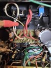
Thanks for the picture, but I think I'm not going to be able to confirm the arrangement from that.
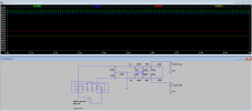

yeah I don't think its a design problem, but a failed component problem. The current being low in the low voltage channel makes me think its supply side, not load-side. One open diode or bad first cap would be my first two thoughts there.
current being high in the high voltage channel may also be a failed component, but probably load-side in that case, so ultimately I think we're looking at multiple problems here.
current being high in the high voltage channel may also be a failed component, but probably load-side in that case, so ultimately I think we're looking at multiple problems here.
I will check the power supply capacitors.yeah I don't think its a design problem, but a failed component problem. The current being low in the low voltage channel makes me think its supply side, not load-side. One open diode or bad first cap would be my first two thoughts there.
current being high in the high voltage channel may also be a failed component, but probably load-side in that case, so ultimately I think we're looking at multiple problems here.
8 volts in pentode mode which is still high unless he ran this amp that high.OK, good deal
now whats the voltage drop across the cathode resistor?
7.6 in triode mode.