• The move to the new server is done. There are some software and database maintenance updates in process. This has us passing the hat around to help out. We appreciate any donations. Seriously, even a dollar helps. The payment page may be found here - https://www.audiokarma.org/support.html

Troubleshooting Help: Tandberg TR-2080

kohlmeyer

New Member
I have a Tandberg TR-2080 that has been part of my collection for awhile, and I am just now getting around to giving it the attention it deserves; it had been relegated to the project pile for the better part of two years.

The issues I had been having:

When I got the unit, the audio output had a minor level of distortion in both channels, and, most frustratingly, the FM signal was completely unstable. When powered on, the relay would click but it would be another couple of minutes before any audio output would pass to speakers. During this time, the distortion could be heard in both channels but no source would throughput audio. After a few minutes, audio output could be heard in the speakers and FM would have the aforementioned instability. In addition to the electrical issues, the AM/FM connection plate on the rear of the unit was broken off.

I was recently able to source a replacement rear-plate from a salvaged Tandberg TR-2080 and have since installed the part. While I had the unit opened up, I decided to attempt to fix the electrical issues. As a start, I heeded some common advice from the AudioKarma archives and replaced all the gold, Frako caps on the Power Amp Board (Qty. 5); replaced the 1000uF63V axial cap on the Voltage Reg board; cleaned the contacts of the relay; performed other general cleaning of potentiometers and wire connectors.

Upon completion of that basic level of service, the output audio was free of noise/distortion and the FM tuner was finally stable. All modes functioned appropriately and sounded great. The caveat to this great news was that it still took a period of time for the audio to throughput to the speakers: between 1 to 3 minutes. During this time, the festoon lamp on the Power Reg board would not glow, but the speaker relay would 'click' almost instantly upon power-up. After some random amount of time, the festoon bulb would alight and everything would seemingly work fine. This, however, has since regressed to longer periods to 'wake-up' the Power Reg board. I tried replacing both the fuse and the festoon bulb, but both were ineffective in resolving the issue.

So, all this leads me here: hopeful to solicit help from the AudioKarma community, in an effort to bring renewed life to my receiver. Admittedly, I am not organically knowledgeable about electronics and troubleshooting electrical issues. I rely heavily on others to help and assist. With that being said, I do have confidence in my competence for soldering, and have the will and the means to source any testing equipment or components that I may need along this journey.

I know this community has a number of Tandberg experts, and I welcome their input, along with any others that may help guide me through this project.

I'll post some pictures of the unit shortly...

Thanks in advance for your time, patience, and any help you may be able to offer me.
 
Register to hide this ad
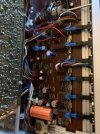
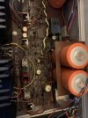
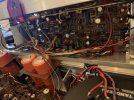
These images were take before the replacement of the gold, Frako caps on the Power Amp board.
 

Attachments

  • IMG_9040.jpeg
    IMG_9040.jpeg
    124.9 KB · Views: 23
  • IMG_9039.jpeg
    IMG_9039.jpeg
    121.7 KB · Views: 23
  • IMG_9038.jpeg
    IMG_9038.jpeg
    129.9 KB · Views: 23
  • IMG_9037.jpeg
    IMG_9037.jpeg
    118 KB · Views: 23
I have a Tandberg TR-2080 that has been part of my collection for awhile, and I am just now getting around to giving it the attention it deserves; it had been relegated to the project pile for the better part of two years.

The issues I had been having:

When I got the unit, the audio output had a minor level of distortion in both channels, and, most frustratingly, the FM signal was completely unstable. When powered on, the relay would click but it would be another couple of minutes before any audio output would pass to speakers. During this time, the distortion could be heard in both channels but no source would throughput audio. After a few minutes, audio output could be heard in the speakers and FM would have the aforementioned instability. In addition to the electrical issues, the AM/FM connection plate on the rear of the unit was broken off.

I was recently able to source a replacement rear-plate from a salvaged Tandberg TR-2080 and have since installed the part. While I had the unit opened up, I decided to attempt to fix the electrical issues. As a start, I heeded some common advice from the AudioKarma archives and replaced all the gold, Frako caps on the Power Amp Board (Qty. 5); replaced the 1000uF63V axial cap on the Voltage Reg board; cleaned the contacts of the relay; performed other general cleaning of potentiometers and wire connectors.

Upon completion of that basic level of service, the output audio was free of noise/distortion and the FM tuner was finally stable. All modes functioned appropriately and sounded great. The caveat to this great news was that it still took a period of time for the audio to throughput to the speakers: between 1 to 3 minutes. During this time, the festoon lamp on the Power Reg board would not glow, but the speaker relay would 'click' almost instantly upon power-up. After some random amount of time, the festoon bulb would alight and everything would seemingly work fine. This, however, has since regressed to longer periods to 'wake-up' the Power Reg board. I tried replacing both the fuse and the festoon bulb, but both were ineffective in resolving the issue.

So, all this leads me here: hopeful to solicit help from the AudioKarma community, in an effort to bring renewed life to my receiver. Admittedly, I am not organically knowledgeable about electronics and troubleshooting electrical issues. I rely heavily on others to help and assist. With that being said, I do have confidence in my competence for soldering, and have the will and the means to source any testing equipment or components that I may need along this journey.

I know this community has a number of Tandberg experts, and I welcome their input, along with any others that may help guide me through this project.

I'll post some pictures of the unit shortly...

Thanks in advance for your time, patience, and any help you may be able to offer me.
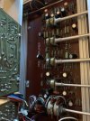
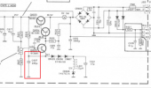
Did you change out this cap on the Regulator Board?
1699390081341.png
 
Did you change out this cap on the Regulator Board?
View attachment 3030005
Thanks for your quick input, Ray. I did not change that cap. If you suspect that to be of issue, is there a way to test whether a capacitor is working or not working by using a standard multi-meter? I've see other posts where - I think - an ESR meter was utilized. Would I need that for proper testing?

As an aside to your question, I can't guarantee that someone hasn't previously been inside the unit and swapped some stuff around. So, if something looks amiss, please let me know.
 
Thanks for your quick input, Ray. I did not change that cap. If you suspect that to be of issue, is there a way to test whether a capacitor is working or not working by using a standard multi-meter? I've see other posts where - I think - an ESR meter was utilized. Would I need that for proper testing?

As an aside to your question, I can't guarantee that someone hasn't previously been inside the unit and swapped some stuff around. So, if something looks amiss, please let me know.
I'm going by you saying that the lamp is taking a long time to turn on. The lamp lights when the regulator pass transistor (Q603) is conducting. If that cap is defective if would match the symptoms.

You can monitor the voltage at its positive end, or the emitter of Q605 and see if it rises slowly to 14 volts.

It may be one of the other caps in there, but that's the one that stands out to me.
 
I'm going by you saying that the lamp is taking a long time to turn on. The lamp lights when the regulator pass transistor (Q603) is conducting. If that cap is defective if would match the symptoms.

You can monitor the voltage at its positive end, or the emitter of Q605 and see if it rises slowly to 14 volts.

It may be one of the other caps in there, but that's the one that stands out to me.
Very good, thanks for the info.

A quick update for the night: I checked the voltage on the positive lead of C607 and it measured at a stable 14.23V DC.
 
Very good, thanks for the info.

A quick update for the night: I checked the voltage on the positive lead of C607 and it measured at a stable 14.23V DC.
Very good, thanks for the info.

A quick update for the night: I checked the voltage on the positive lead of C607 and it measured at a stable 14.23V DC.
OK. Check voltages at Q603, 604 and 605. Until Q603'e emitter is putting out +25 volts the circuit isn't working. I was suspicious of C607, but C609 could be an issue. The voltages you take will point the way.

Be very careful not to slip with the DMM probe while taking measurements. Many folks wrap black tape around all but the very tip of the positive probe to prevent shorts.
 
OK. Check voltages at Q603, 604 and 605. Until Q603'e emitter is putting out +25 volts the circuit isn't working. I was suspicious of C607, but C609 could be an issue. The voltages you take will point the way.

Be very careful not to slip with the DMM probe while taking measurements. Many folks wrap black tape around all but the very tip of the positive probe to prevent shorts.
Here is the additional data:

E of Q603 = 1.75V
E of Q604 = .1V
E of Q605 = 14.24V

+ of C609 = 45.2V

Thanks again for your help!
 

Attachments

  • IMG_9048.jpeg
    IMG_9048.jpeg
    137.3 KB · Views: 10
You didn't get the base and collector voltages (some of these are common to each other).
Sorry about that. Here is the complete dataset:

E of Q603 = 1.75V
E of Q604 = .1V
E of Q605 = 14.24V

B of Q603 = -1.5V
B of Q604 = 43.5V
B of Q605 = 12.4V

C of Q603 = 43.7V
C of Q604 = 43.8V
C of Q605 = 43.5V

+ of C609 = 45.2V
+ of C607 = 14.23V
 
Thanks for your help. I will try to source an appropriate transistor to replace the suspect part.

To that end, is there a material difference between a transistor marked BC549CS and BC549C? My copy of the service manual references BC 549C for Q604, but the part in the unit is marked BC549CS. It's my first time shopping for transistors, so I just want to make sure I'm not making any rookie mistakes that could compromise the unit.

The unit I had salvaged some parts from seems to contain different iterations of some of the boards. Among other differences, the Power Amp board doesn't have "Mk II" printed on it and the Q604 transistor is marked as BC238C. So, I'm reluctant to transplant that part if a new, appropriate transistor can be easily obtained.

Again, thanks for your time and assistance!
 
I'm in the replace all electrolytic capacitors more than 30 years old camp of electronics repair. I've found that it saves many hours of frustration with intermittent and marginal problems. Q603 does the heavy lifting and sees the most current and if it's heat sinking to the chassis wasn't great that may have stressed it beyond usability. Its also conceivable that the trim pot has gone flaky as those pots have been a problem on older Revox tape machines but I've never seen them go bad in Tandbergs.
 
Thanks for your help. I will try to source an appropriate transistor to replace the suspect part.

To that end, is there a material difference between a transistor marked BC549CS and BC549C? My copy of the service manual references BC 549C for Q604, but the part in the unit is marked BC549CS. It's my first time shopping for transistors, so I just want to make sure I'm not making any rookie mistakes that could compromise the unit.

The unit I had salvaged some parts from seems to contain different iterations of some of the boards. Among other differences, the Power Amp board doesn't have "Mk II" printed on it and the Q604 transistor is marked as BC238C. So, I'm reluctant to transplant that part if a new, appropriate transistor can be easily obtained.

Again, thanks for your time and assistance!
Test them before you just replace them.
 
Basically, at the very moment of power on, the BC238C is for too low a voltage, as is BC549C. At the moment of power on, it is above the specified 30 Volts CB voltage If you have to buy something, use BC550C (which did not exist back then I think, although they could have used BC413 as they did mix BC413 and BC549 in my TR2075....).
A lot of people use BC550 to replace any of the BC547,548 or 549

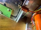
Now, for the Q603, if it is connected by a connector which can be slid on it, make sure it makes good contact. (and if it is not connected wrong way around)
A problem here could cause Q603 and/or Q604 to fail.

The measuring done as stated:
E of Q604 = .1V
B of Q603 = -1.5V

As B of Q603 is connected to E of Q604 suggest redo the measuring.
 
Basically, at the very moment of power on, the BC238C is for too low a voltage, as is BC549C. At the moment of power on, it is above the specified 30 Volts CB voltage If you have to buy something, use BC550C (which did not exist back then I think, although they could have used BC413 as they did mix BC413 and BC549 in my TR2075....).
A lot of people use BC550 to replace any of the BC547,548 or 549

Now, for the Q603, if it is connected by a connector which can be slid on it, make sure it makes good contact. (and if it is not connected wrong way around)
A problem here could cause Q603 and/or Q604 to fail.

The measuring done as stated:
E of Q604 = .1V
B of Q603 = -1.5V

As B of Q603 is connected to E of Q604 suggest redo the measuring.
Very good observation, gslikker! I had actually taken that measurement - B of Q603 - from the related pin that protruded from the bottom of the connector. Taken at the solder joint on the board, the values are identical: E of Q604 = B of Q603 = .1V.

I’ll remove Q604 to test and will report back.

Thanks for everyone’s help.
 

Attachments

  • IMG_9062.jpeg
    IMG_9062.jpeg
    101 KB · Views: 10
Last edited:
Very good observation, gslikker! I had actually taken that measurement - B of Q603 - from the related pin that protruded from the bottom of the connector. Taken at the solder joint on the board, the values are identical: E of Q604 = B of Q603 = .1V.

I’ll remove Q604 to test and will report back.

Thanks for everyone’s help.
I removed the suspect transistor this morning. Based on my understanding - from reading around online - this NPN transistor should show a voltage drop between the Base and the Emitter, when hooked to a multi-meter. During testing, when I hooked the positive lead to the Base and the negative lead to the Emitter, I received an OL reading. I think this is indicative of a bad transistor.

I will source some replacement transistors, per gslikker's recommendations, and will report back once received and installed.
 
you're on diode check mode ? One direction should be open, the other direction should be around 0.6 volts if its good. If its open both ways, its dead.
 
Back
Top Bottom