filmis
Active Member
Since my new Nakamichi amp has a bunch of digital inputs, I've been trying to make the most use of them as the DACs on there really sound fantastic.
I'm modding a Denon LA-2150K laserdisc to output the digital audio (yes, most laserdiscs had digital audio, though it was also analog-capable).
Luckily, the onboard CXD2500AQ DSP offers pin 60 as TTL-level S/PDIF digital signal. Holding pin 59 high enables the digital output and I get a good, strong signal.
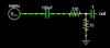
I'm trying to troubleshoot the attached circuit. Those resistor values should provide the desired change in voltage range, from 0,5V to the required -0.5,0.5V. However the actual output ends up being more like 0-1V and doesn't seem to dip below zero. Naturally my DAC refuses to do anything with this.
I'd like to keep the component count low for now--just a proof of concept will suffice for now--but is there any obvious fault or alteration I should make?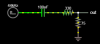
I'm modding a Denon LA-2150K laserdisc to output the digital audio (yes, most laserdiscs had digital audio, though it was also analog-capable).
Luckily, the onboard CXD2500AQ DSP offers pin 60 as TTL-level S/PDIF digital signal. Holding pin 59 high enables the digital output and I get a good, strong signal.
I'm trying to troubleshoot the attached circuit. Those resistor values should provide the desired change in voltage range, from 0,5V to the required -0.5,0.5V. However the actual output ends up being more like 0-1V and doesn't seem to dip below zero. Naturally my DAC refuses to do anything with this.
I'd like to keep the component count low for now--just a proof of concept will suffice for now--but is there any obvious fault or alteration I should make?