
• The move to the new server is done. There are some software and database maintenance updates in process. This has us passing the hat around to help out. We appreciate any donations. Seriously, even a dollar helps. The payment page may be found here - https://www.audiokarma.org/support.html

Tube Matching - TV-7 vs Plate Current

Walter R

Active Member
There are two methods commonly used to perform tube matching, using a tube tester or by measuring in-circuit plate current. The tube tester would seem preferable, but my TV-7 measures transconductance at a plate voltage of 150 vdc while the in-circuit plate voltage is nominally 440 vdc. So I decided to perform a test, checking the tube matching by both methods.

My bedroom stereo consists of two monaural integrated amplifiers, an Eico HF-20 and an HF-20 clone made by Elmat. Each amplifier uses two 6L6GC output tubes in push-pull operation, which are the tubes that were checked. At the start of the testing, all the tubes were J/J manufacture.

My TV-7B was recently repaired and calibrated by Daniel Nelson, so it is in good shape. I checked the in-circuit plate current by using a quadruple socket current meter I obtained from China.

The first table shows the result of the testing with the original tubes. In the Elmat amplifier, both methods indicated that the tubes were reasonably matched. However, in the Eico amplifier, the TV-7 indicated that one of the tubes was near failure and the other had a test reading that was 16% higher. But the in-circuit plate current indicated that the tubes were matched.D07BB5F9-FBD7-4B11-AEED-5DAF89D6B464.jpeg
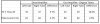
I replaced the tubes in the Eico amplifier with two new Russian Tung Sol “matched” tubes, straight out of the box. Then I repeated the test for the Eico amplifier, with the results 0BF39814-CAC6-4171-97F5-B23EC11A0A8B.jpeg shown in the second table. The plate current method showed better matching than the TV-7.

My personal conclusion is that I trust the tube tester method more for tube matching. The plate current method may be adequate for comparing new tubes but fails when checking used tubes.
 
Register to hide this ad
Thanks for posting this - I assume you were measuring the plate current, not the cathode current that a number of people use?

On this note of "in circuit testing": One thing a lot of people do not realise is that measuring cathode current is not accurate, especially with tetrodes since the screen current can vary widely and hence when added to the plate current (as when measuring the cathode current) can be misleading. Measuring plate current with the high voltages is dangerous if one does not know exactly what the risks are and how to safeguard oneself. Be careful and stay safe, even the best performing amplifier will be of no use to you if you have departed from this world.
 
The Chinese tester I used to measure the in-circuit plate current has four test sockets that plug into the amp between the tubes and the amp socket. The test sockets are hard wired to a digital milliammeter. So I was never exposed to the plate voltage. I thought of measuring the plate current while in the tube was in the tube tester, but didn’t go that far.
 
Well, there's definitely two different factors going on here- plate current, and transconductance!

These two factors oftentimes do NOT correlate- in fact, that's the primary reason,why both figures are given, when tubes are purchased as matched sets.

The TV7 is better at matching the transconductance- but, there's nothing in it, that really gives any significant insight into plate current.

if the TV7 said the tubes were unmatched in transconductance- I would hedge a bet, that if the AC behavior of the amp was measured, with those tubes installed- especially measured for even-order distortion without the feedback connected- there would be significant evidence of an AC gain imbalance- high level of even-harmonic distortion in a PP amp. Even with the idle current matched- a DC balance- the AC balance would still be compromised.

Regards,
Gordon.
 
@GordonW In days past I used to have a Marconi distortion factor meter and I found that one may have the ideal output tube balance but by the time the driver tube was taken into account the balance went out the window. I ended up doing what the military recommended: testing through the amplifier by applying an input signal and measuring the output signal. I used an adjustable floating paraphase inverter and more than halved the overal distortion by adjusting the inverter. But it had the drawback that tubes could not be moved around.

I am a great believer in using cathode bias (in spite of less output) and having the cathode resistor adjustable. Since running the tubes pretty hot I adjust for equal plate current in order not to exceed design centre maximum plate dissipation.

These days I prefer SE with not too much negative feedback as I perceive a more life like reproduction. (overal synergy of amplifier - speakers) There seems these days also to be a bias against SRPP but if configured correctly it can offset the non-linearity of the output stage. Often this means that in spite of the distortion in the indivdual stages going up the overal distortion goes down. One has to consider the whole in addition to the individual parts. At the moment I am working on a design which seems to be very promising - only local feedback in the output stage and a SRPP driver stage and ending up (in simulation) with 1.27% distortion at onset grid current and at 1 watt around 0.25% distortion. If the same design was to use global negative feeback from the secondary of the output transformer I would have higher distortion at 1 Watt, simulation suggested around 0.8%.

Many people do not realise that there are three levels of plate dissipation specifications in use but these days only two are commonly used: design centre and absolute maximum. Absolute maximum is in general design centre + 10% in both dissipation and voltages. Between design center and absolute maximum tube life deteriorates considerably. Going below design centre does not increase life by the same margin, the KT66 datasheet specifies at design centre 8 000 hrs and at 70% of design centre it increases to 10 000 hrs minimum life expectancy. Design center was so called in order to incorporate component changes and mains power fluctuation, absolute maximum means that under no circumstances should the rating be exceeded.
 
Back
Top Bottom