• The move to the new server is done. There are some software and database maintenance updates in process. This has us passing the hat around to help out. We appreciate any donations. Seriously, even a dollar helps. The payment page may be found here - https://www.audiokarma.org/support.html

Two Issues on 800c

First, my apologies to the group for not being more involved as the designer of the "IBAM". My current schedule only allows me to be an occasional lurker here. I still do intend to produce a document for the mod.

The mod is not sensitive to where where the ground is as long as it is a solid chassis ground. I believe you have fixed that problem.

Did you put the four 33uf caps in? Did you remove the original electrolytic cap? These caps are very important for suppressing the 180hz hum. If you left in the old cap, did not install all four caps, attempted to use one big cap, or put one big cap in the wrong place you will get hum.

How bout some pictures?

There he is! I finally listened and installed your IBAM mod on my 800B and what can I say, should of just did it the first time. :D Works beautifully. :thmbsp:

Kory
 
There he is! I finally listened and installed your IBAM mod on my 800B and what can I say, should of just did it the first time. :D Works beautifully. :thmbsp:

Kory

Thanks to all who have put up with my hit and miss involvement. Unfortunately I am off the Choo-choo town and wont be back until October 3rd.

I just noticed that the cap needing removal in the 800c is a 0.1uf mylar (C92 on my schematic). Also note that my design also replaces C14 and C15. The reason for replacing the 0.1uf with a dramatic increase (132uf total) in value is taken from the last fixed bias design Fisher had in the 400. Yes, the 400 was the last of the series in spite of the lower model number.

I had always noted a 180hz spike on my spectrograph. On a whim I tried the 400 bias design and watched the spike disappear. Looks like the Fisher engineers finally solved the problem, no reason we shouldn't also.
 
Hello Drew...
First, I wanted to thank you for your contributions here and in the tube forum.
I gleaned much from your past posting...much is over my head still, but now understand more than I did 4 months ago.

I'm running original Fisher 7591's

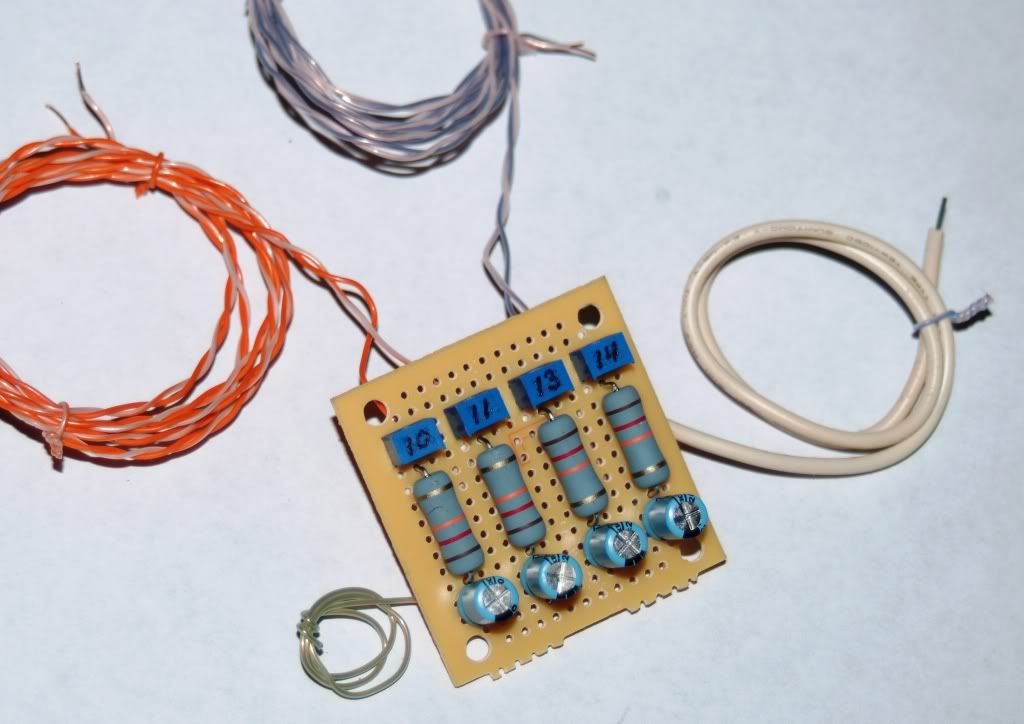
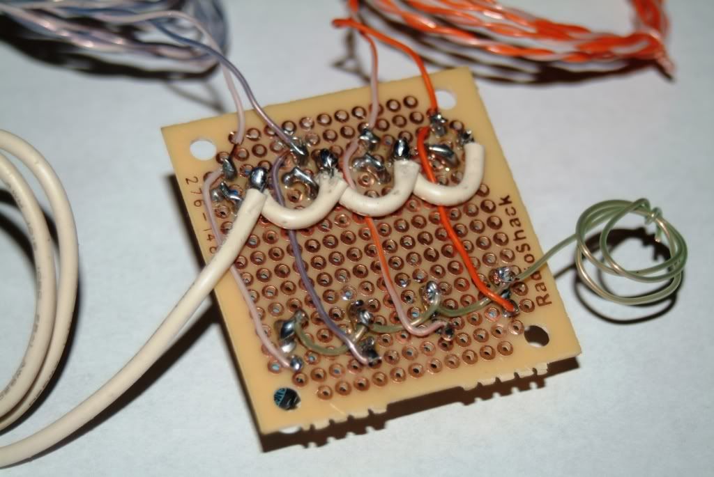
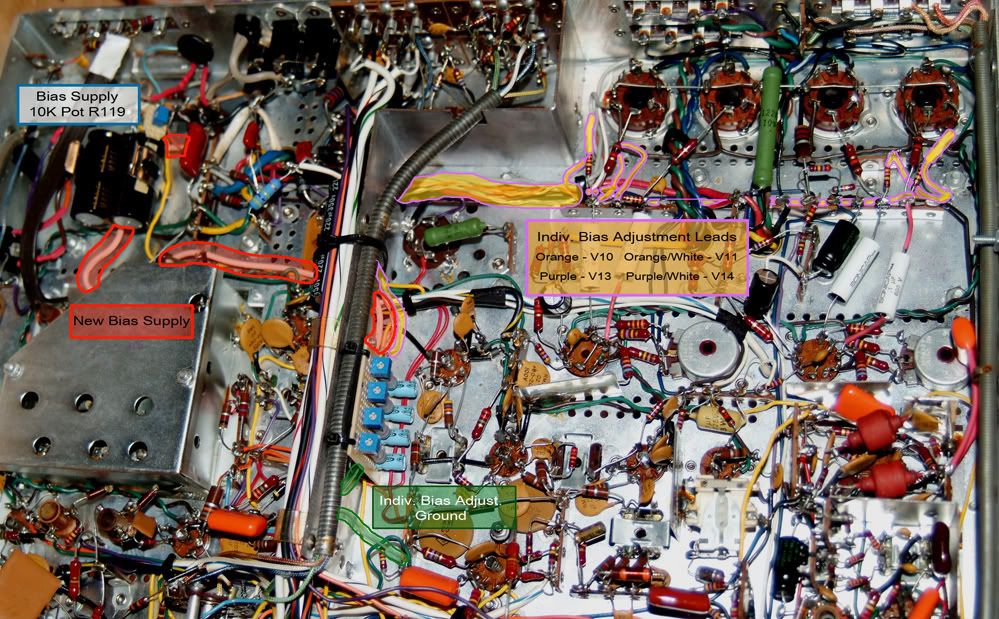
Pictures I got...

...from here. http://www.audiokarma.org/forums/showthread.php?t=373498

IndBiasSupplydiag.jpg


IBPMFront.jpg


IBPMBack.jpg


IBPMinstalled3markedupflat.jpg


Good to see you here again

martin
 
Yes Larry...
In the post just before yours, I stated just that very fact, that when I move my hand over various areas, the pitch does change...are you onto something?
Please share.
martin
 
Drew...
On my 800c, C92 (replaced in metalbones restore), C14 & C15 (original ceramics)are still in. You recommend removal?
martin
 
Drew...
On my 800c, C92 (replaced in metalbones restore), C14 & C15 (original ceramics)are still in. You recommend removal?
martin

Keep C14 and C15 (I usually put them on my bias boards) since they are not on your new board. Remove C92, it is replaced by the electrolytics.

I think I see the source of your hum. Pot R119 is not used in my circuit. It introduces a second ground and quite possibly creates a ground loop. Of course you will need to "0" the pots and redo your bias adjustments since the power supply will now be hotter.

I remember one guy who noted that the drain wire in the shielded wires (the ones with the stripes running down the center from front to rear) was open on one end. He dutifully soldered them to ground and the thing hummed like banshee. Sniping the one end (restoring the original shielding) removed the ground loop.
 
Will give it a go.
But let ask this.
If this is the reason I'm getting hum in my phono / tape sections, wouldn't it also show up in the aux and tuner section as well?
They are dead quiet.

Just curious.:scratch2:

Martin
 
Will give it a go.
But let ask this.
If this is the reason I'm getting hum in my phono / tape sections, wouldn't it also show up in the aux and tuner section as well?
They are dead quiet.

Just curious.:scratch2:

Martin

Good point. However hum is tricky. The extra gain stage and the mv signal level could just be exposing it. I suggest you replace the 10 ohm ground "lifter" resistors R149 and R151. I have found those can be the source of hum and noise.
 
Once I get new batteries for my camera, I'll put up a pic of the underside of the 800C with the IBAM. I modified an angle mount, and soldered it to the isolation plate right above V10. Then bolted the IBAM to it.

Larry

As promised. On the 400 I made a buss bar to the Grids and installed 100oHm resistors (per Dave Gillespie's article). The height is about 1/3" or the length of the 1/2W resistor body. Removed the original wiring, which opened up some ventilation holes. I'm running 38ma @ 375 plate voltage for 14.25W per tube. (7868's) The 330K resistors were replaced with 200K on both the 400 and 800C. Both work fine.
attachment.php


attachment.php


On the 800, I took a scrap piece of sheet metal, and made a mounting bracket. Drilled two holes, and then soldered the bracket to the RF shield just to the left of V10. Bolted the IBAM module to it and ran the leads. I'm contemplating a buss bar with 100oHm resistors for the grids like the 400. 38ma @ 415 plate voltage for 15.75W per tube. 330K resistors replaced with 200K.
attachment.php
 

Attachments

  • 400 IBAM MODS overall.jpg
    400 IBAM MODS overall.jpg
    150.5 KB · Views: 311
  • 400 IBAM MODS.jpg
    400 IBAM MODS.jpg
    133.5 KB · Views: 1,660
  • 800C IBAM MODS.jpg
    800C IBAM MODS.jpg
    137.2 KB · Views: 1,146
Last edited:
Larry, clean and tight and everyone else...

IBAM = Individual Bias Adjustment Mod
as per Drew's original schematic.

You can keep the trifocals Larry...you seem to need them more than me. :D

martin
 
Okay...

I removed C92 and it seems to have made no difference in the hum or in my final numbers.

Which are...
R119 (pot...yes, still) -18.09

V10
pin3 436
pin4 391
pin5 34.0 mA
pin6 -16.70 V

V11
pin3 436
pin4 391
pin5 34.10 mA
pin6 -17.07 V

V13
pin3 436
pin4 391
pin5 34.10 mA
pin6 -17.13 V

V14
pin3 436
pin4 391
pin5 34.00 mA
pin6 -17.41 V

My only question is the -18.09 at R119. If I move it closer to -17.00 as spec'ed It pushes my pin 5 numbers into the 36.xx mA range.
I would use the IBAM to adjust the current, but my V14 pot is maxed out.
I'm happy with the numbers as long as assured that -18.09 at R119 is having no ill affect elsewhere.

martin

p.s. will look into picking up some replacement resistors for R149 & R151
 
Last edited:
Okay...


My only question is the -18.09 at R119. If I move it closer to -17.00 as spec'ed It pushes my pin 5 numbers into the 36.xx mA range.
I would use the IBAM to adjust the current, but my V14 pot is maxed out.
I'm happy with the numbers as long as assured that -18.09 at R119 is having no ill affect elsewhere.

martin

p.s. will look into picking up some replacement resistors for R149 & R151

If V14 is maxed out (I don't know which direction you mean, I assume it is pegged and you cannot reduce the current any further) it most likely means the tube is flaky or about to fail. Does the value change as you adjust the pot? I have had bad solder joints on perf boards (the pads are notorious for lifting off with heat). The design should put most tubes about midrange on the pot with a 30-35ma current draw. Also, check your 10 ohm resistor. I have seen them blow partially and go way off in value.


At the risk of being crude I don't think you are getting the point of the IBAM. The -17v on the schematic is a reference value for troubleshooting, nothing more. The IBAM design completely changes the voltage and makes any reading invalid. Put a red line thru it on your schematic.

At that voltage the power tubes are run extremely hot and would burn out after about a year of normal usage. This was acceptable when the tubes where $1.00 apiece. Running them this hot also negated the variations between tubes and allowed for a design with no adjustment.

The whole purpose of the IBAM is to eliminate the non-adjustable bias and incorporate a balanced adjustment based on the real measurement. The current draw of the tube as measured across the 10 ohm resistors allows us to measure and balance individual tube current draw at idle. This allows us to run the current draw lower for better tube life and accommodate mismatched tubes.

Leaving R119 accomplishes nothing. Measuring the voltage at R119 has no purpose. Leaving it is quite possible setting up a ground loop that is buzzing thru the entire chassis ground plane.
 
Last edited:
One more thought. Trying swapping tubes. If the current draw on V14 remains maxed out there is a problem with the bias circuit, if it follows the tube then the problem is the tube. You may also find that the tube has a particular socket in which it behaves.
 
I just now zoomed in on your chassis picture. Just an observation, you left in the original 330k resistors (orange, orange, yellow) while you changed the coupling caps to 0.1uf. These two are linked in desired value. If you put in 0.1uf you should change the resistors to 200-220k.

This should have nothing to do with the hum but can affect the sound stage and power tube life.

It will also change the setting of the pots and may account for your out of range tube.
 
Martin;

Well, the nOOb did it again. Didn't have my glasses on. Edited my previous post instead of quoting it. So the Pictures of my 800C and 400 are there on Page 2. POST #29.

Larry
 
Last edited:
Here's an article from Dave Gillespie on improving Power Tube life. As I found a lot of it over my head, and Dave was available for questions on this in another forum, he got bombarded...hehe. Upshot is the 100R 1/2w on the screen of the 7868's on the 400.

Larry
 
Last edited:
Okay...
This is coming from a noobs point of view...so, let the beating of the dead horse begin.

Drew, thanks for arresting my attention and causing me to consider what I knew about the function of the IBAM. Your explanation will help a lot of us noobs.
What I didn't grasp, is what it actually does circuit wise and why it replaces some existing components. It's just my lack of understanding electronics. I'm destined for the life of a hobbyist at best.
Larry did try to help me at one time with the removal of nonessential components associated with the IBAM , but my numbers only got worse.
I believe that was due to the fact that my incorrectly terminated IBAM ground wire was going through R132 / 330K to get to ground...maybe...I don't know...perhaps. :scratch2:

So after a bit of rereading old post and emails, I "think" I get it a little better. Just don't ask me to explain it.

Anyway...the pot at R119 is gone (can I get an "amen"?), R119 is nonexistent for that matter, as is C92 and R122 (as per Larry's suggestion). I tried R122 in and out of circuit and only made marginal difference in the numbers, but I think the sound is better with it out.

I also replaced the 330k resistors with 200k's

As a result, everything is better. My IBAM pots are all just a bit off center point with room to spare either direction...as they should be. :thmbsp:
Everything is as it should be.


So I think these are my final numbers

AC line 119.8

V10
pin 3 435V
pin 4 392V
pin 5 35.0mA
pin 6 -16.54

V11
pin 3 435V
pin 4 392V
pin 5 35.00mA
pin 6 -17.05

V13
pin 3 435V
pin 4 392V
pin 5 35.10mA
pin 6 -17.10

V14
pin 3 435V
pin 4 392V
pin 5 35.00mA
pin 6 -17.40

I arrived at 35.00mA by...

435V multiplied by .035mA = 15.22 watts
80% of the 19 watts spec'ed for the 7591 =15.20 watts
(19 divided by 5 = 3.8 times 4 (80%) = 15.20)
According to Jim McShane...thanks larry

Did I get it right?

Drew...I replaced R149 and R151 and it did help resolve some of the hum issue...thanks.

The hum is only audible at volumes beyond my listening range...that's good enough for me.

Thanks guys for putting up with me.

The 800c sounds awesome!

martin

P.s. How many times am I going to finish this 800c?
 
Last edited:
Okay...
So I think these are my final numbers

AC line 119.8

V10
pin 3 435V
pin 4 392V
pin 5 35.0mA
pin 6 -16.54

V11
pin 3 435V
pin 4 392V
pin 5 35.00mA
pin 6 -17.05

V13
pin 3 435V
pin 4 392V
pin 5 35.10mA
pin 6 -17.10

V14
pin 3 435V
pin 4 392V
pin 5 35.00mA
pin 6 -17.40

I arrived at 35.00mA by...

435V multiplied by .035mA = 15.22 watts
80% of the 19 watts spec'ed for the 7591 =15.20 watts
(19 divided by 5 = 3.8 times 4 (80%) = 15.20)
According to Jim McShane...thanks larry

Did I get it right?

Drew...I replaced R149 and R151 and it did help resolve some of the hum issue...thanks.

The hum is only audible at volumes beyond my listening range...that's good enough for me.

Thanks guys for putting up with me.

The 800c sounds awesome!

martin

P.s. How many times am I going to finish this 800c?

AMEN!!!!!!!!:D

FANFREAKINTASTIC!!!!!!!! Numbers look good. They will vary slightly as your line voltage goes up and down. but they look good. You're getting it (Guess Drew's slap on the back of the head works better than mine, LOL!). Now all you need to do is take the basic electronics course given by Thomas Edison and George Westinghouse, with guest appearances by Nickola Tesla. :D :naughty: :D :naughty: :D

You'll NEVER be finished with the 800C. It's like owning a Classic Car. It's addictive, but non narcotic. However it sucks up $$$ faster than a $2.00 hooker during Fleet Week in Seattle or San Francisco. There are little improvements or tweaks out there that can be done, but it's up to the individual whether he/she/?? wants to implement them. Parts eventually wear out or die. I just had to replace the 1800pf cap on the diode board near the mpx the other day. And that was after 6 hours of troubleshooting and signal tracing. Took 5 minutes to replace.

I'm thinking about putting pin jacks on mine next to each 7591, so I can check the ma from the top. Also, maybe........just maybe, individual pots thru holes in the deck so I can adjust the bias from the top too. I did the pin jacks on my 400 and it's real nice to be able to check the draw while running and not have to tear it all down.

Boutique caps, boutique resistors, tube rolling......they are all part of the experience. How far you want to travel down the road is up to you.

But for now, kick back on the sofa with a COLD Drink, the dog at your feet, and a hot babe at your side(preferably the wife....... :D ), lights turned down low and CRANK IT UP! Play something SHE likes 1st.

Enjoy the hell out of it. Let everything settle in (caps, tubes, resistors,etc) for a couple weeks. It'll open up some as the parts settle in.

You did good for a 1st timer. You took a piece of gear that had problems and with some help via internet,(nobody sitting over your shoulder) YOU got it running well, and able to enjoy it. Not everyone can do that. Don't be ashamed about the questions you asked. We all asked them at one time or another. Some of us with thicker skulls still do. One of these days you be answering the questions and not even realize when that happened. It's a constant learning experience. Always something new out there, and the old stuff doesn't always get passed down, so it has to be re-learned by a new generation. And when that happens, you'll get a warm,fuzzy feeling in the pit of your stomach and think......"Jeez, I was there once."

Larry

 
Martin,

You're light years ahead of me when I first started tinkering with this stuff. I think half the time the biggest thing is confidence. You had a very good idea what you were doing all along but just weren't quite sure in yourself yet. I bet you could rebuild another 800C in about half the time with the confidence and knowledge you now possess.

The question for you since I know you're into good beer...what are you drinking while listening to that better than new 800C???

I'm sipping on a Lagunitas Bavarian-Style Doppel Wiezen right now in celebration for tracking down some gremlins in the gear I'm currently working on.

I know it's over already but Larry is one guy I think ought to get a few votes for AK'er of the year next year. If you weren't retired, I'd say helping people at every turn on here is darn near a full time job for you. Just another reason I love this place. :thmbsp:

Kory
 
Thanks guys...
I still have her out of the case to watch her for a while. She seems to be holding pretty steady.
I just went through all the tubes and documented their strengths. Even though it's only an emission tester, it at least tells me their all good.
All my 12AX7s measured the same, except for the one that exhibits signs of microphonics, however the strength is only slightly less.

The only tubes I couldn't find listing for in my testers charts are 6GK5 (V1, V9) and 6HR6 (V3).

Do all tube testers use the same charts or are they tester specific? In other words does a Hickok, B&K and so on list the same Fil. volts / Sensitivity / F, N, and P, numbers? I have no experience with other testers, so I can only use mine as a reference. Hope that makes sense.

Larry...
I really appreciate the effort you put in, trying to explain the need to get rid of the components that the IBAM replaces. After going back over your emails, you were quite clear and everything I needed was there.
For some reason I couldn't wrap my head around it. Probably because I was still worried about that neg. bias voltage misconception.
Between your emails & posting Jim McShane's formula (ohm's law), Drew's explanation and getting my IBAM ground right, it worked for me.

Kory...
I couldn't agree more. Larry has really put forth a tremendous effort to help everybody here in the Fisher forum, both online and in the field. I'd take a road trip with him to pick up some gear. I'm sure I could learn a thing or two.

Kory, I'm off beer for a while...trying to shed a few lbs. But what your having sounds like the ticket. My favorite is Red Irish Ale (drooling). You ought to give homebrewing a try. I think you would do well.
You have that attention to detail that produces a good finished product (more drooling).

Like most hobbies (or any work) that have a desired end result, after you achieve it, you get that sense of accomplishment...a good feeling for sure...and leaves you with something to enjoy after the labor is finished.

martin
 
Last edited:
Back
Top Bottom