• The move to the new server is done. There are some software and database maintenance updates in process. This has us passing the hat around to help out. We appreciate any donations. Seriously, even a dollar helps. The payment page may be found here - https://www.audiokarma.org/support.html

Two Issues on 800c

Thanks for the Kudo's guys. But I'm a rank amateur (read nOOb) when it comes to electronics. It takes some time for me to understand most things, but once I get it, it sticks. But I'm NO TECH. Just a guy who enjoys the challenge of getting a piece of gear working, inexpensively, and to spec as much as I can with the tools at hand. Like most all of you I enjoy working on the electronics, but the cabinetry gets the best of me at times. I like to think I pass on as much as or more than I've gotten here to help those who have similar problems based on my experiences, and what I've learned here on AK. But PLEASE, NO NOMINATIONS for AK'er's of the year. I'd rather stay in the background (such as it is).

I'm working on getting what appears to be a '57 EBONY C.E. II but now may be an Earlier model based on the description of the Model # of the receiver. I'll know what it is by the middle of next week when we can get together. I'm getting like a kid on Christmas eve waiting for morning to come. Can't wait!!!

Larry
 
I just had to replace the 1800pf cap on the diode board near the mpx the other day. And that was after 6 hours of troubleshooting and signal tracing. Took 5 minutes to replace.Larry


What type of cap did you use in that spot, Larry?

I am in the middle of finishing off the random caps in mine between doctor visits and was just eye balling that little polystyrene today, debating whether to disturb it or not. Did you do the small .047s as well in the MPX section on yours?

Spent quite a bit of time shoe horning .1uF 716Ps where all those little 0,1uF Hollands were!

Thanks
 
Last edited:
Martin,

While you have your 10 ohm resistors out let's complete the IBAM.

I noticed from your current calculations and photo that you have not installed the 10 ohm "cathode fuse" resistors. These are an important part of the IBAM circuit. They provide the only accurate current measuring point. They also protect the output transformers from bad output tubes.

Current can only be accurately calculated from the voltage measured at the 10 ohm resistor to chassis ground with the volume control at minimum. Per ohms law we are looking for 0.350 volts which is the 35ma you are looking for.
 
What type of cap did you use in that spot, Larry?

I am in the middle of finishing off the random caps in mine between doctor visits and was just eye balling that little polystyrene today, debating whether to disturb it or not. Did you do the small .047s as well in the MPX section on yours?

Spent quite a bit of time shoe horning .1uF 716Ps where all those little 0,1uF Hollands were!

Thanks

All I had at the time were 4 WIMA 470pf poly's (They metered out to 1872pf paralleled). Paralleled them until I can get an 1800 in there. I turned it on one day and found the volume was really low, damned near non existant in FM and AM. Phono, AUX, and Tape were fine. Hell of a time tracking down the problem. I had changed one of the resistors near it, and probably got the iron too close to it, which opened it up (electrically) and I didn't realize it. Spent 5-6 hours tracking it down, and 5 minutes changing it out. I didn't change any thing out in the mpx, but a P.O. had (the .047's) so I left sleeping dogs lie.

for the .1uf's I went mostly DME's or CD axials. As i can't really tell the difference in sound, I put the DME's in as they are cheaper. I like how they sound so that's another plus.

MARLOUBOW

The only tubes I couldn't find listing for in my testers charts are 6GK5 (V1, V9) and 6HR6 (V3).

Do all tube testers use the same charts or are they tester specific? In other words does a Hickok, B&K and so on list the same Fil. volts / Sensitivity / F, N, and P, numbers? I have no experience with other testers, so I can only use mine as a reference. Hope that makes sense.

In a word no. There may be some similarities between models of the same manufacturer, but generally not. The 6HR6 is similar to a 6HS6 try that. My EICO 625 doesn't list the 6HR6, but I got a good reading on the 6hs6 settings. If your's doesn't list the 6HS6 try 6AU6. As for the 6gk5 try a 6ER5 or 6FQ5A if your tester lists those. The tubes I've listed are the preferred subs, so they may work. Put this link in your favorites....... http://www.nj7p.org/Tube.php


Larry
 
Last edited:
Drew...
Isn't that what these are?

IBPMinstalled4-1.jpg
 
[B said:
MARLOUBOW[/B]


In a word no. There may be some similarities between models of the same manufacturer, but generally not. The 6HR6 is similar to a 6HS6 try that. My EICO 625 doesn't list the 6HR6, but I got a good reading on the 6hs6 settings. If your's doesn't list the 6HS6 try 6AU6. As for the 6gk5 try a 6ER5 or 6FQ5A if your tester lists those. The tubes I've listed are the preferred subs, so they may work. Put this link in your favorites....... http://www.nj7p.org/Tube.php


Larry


Larry...
Thanks for posting those for me. No listing for the 6GK5 substitutes.
The 6au6 was the only one for the 6hr6 and it took my meter the wrong direction. :no:

Guys, I really think I done with this for the time being. Everything is working very well. The hum is almost non existent. My numbers are holding true. Tubes are strong.
There's nothing that I feel unsure about. Nothing that I'm second guessing. I think I'm good to go. :thmbsp:

Thanks again...for the gazillionth time!

See ya' on the other side boys!

Martin
 
Mine has a subtle NO SIGNAL hum if I turn it all the way up and I sit 3" away from the speaker. It's inherent in most designs. As long as it stays that way, don't worry about it.

Sorry to hear about the tester #'s. But you CAN sub a 6AU6 for the 6HR6. I've done it with that tube and the 6HS6 with no detrimental effects. Keep the Sub numbers handy. Also the 6AQ8. Sub is a 6DT8. It works and costs about 1/5th of a 6AQ8.

Larry
 
They were...pin side of 10ohm resistor
martin

Sorry for the misunderstanding. When you posted ma instead of voltages and I did not see the resistors I assumed you were trying to directly read current.

The 6GK5 just powers the stereo beacon relay. If the light works correctly the tube and associated circuitry are fine.

The 6HR6 is another matter. You really cannot sub a 6AU6 here. If your FM can pick up a weak signal and tunes correctly it is most likely good.

Besides swapping tubes in the IF or MPX sections require realignment. Leave them be if it is behaving.

Sit back and enjoy the music.
 
Drew...

Everything is behaving itself...so I feel good about those areas at present.

thanks

martin

P.s. No more Bobby Fisher impersonations Drew...this forum needs your kind of expertise. :D
 
First, my apologies to the group for not being more involved as the designer of the "IBAM". My current schedule only allows me to be an occasional lurker here. I still do intend to produce a document for the mod.

The mod is not sensitive to where where the ground is as long as it is a solid chassis ground. I believe you have fixed that problem.

Did you put the four 33uf caps in? Did you remove the original electrolytic cap? These caps are very important for suppressing the 180hz hum. If you left in the old cap, did not install all four caps, attempted to use one big cap, or put one big cap in the wrong place you will get hum.

How bout some pictures?

Uh oh! :worried:
So when we get our IBAM assembled, besides the original two resistors on the white wire, what cap is it we need to remove? Ours is a 500-C with the Sheldon Stokes board.
We thought we understood it! :no:
Phyllis
 
Hello Drew...
First, I wanted to thank you for your contributions here and in the tube forum.
I gleaned much from your past posting...much is over my head still, but now understand more than I did 4 months ago.

I'm running original Fisher 7591's

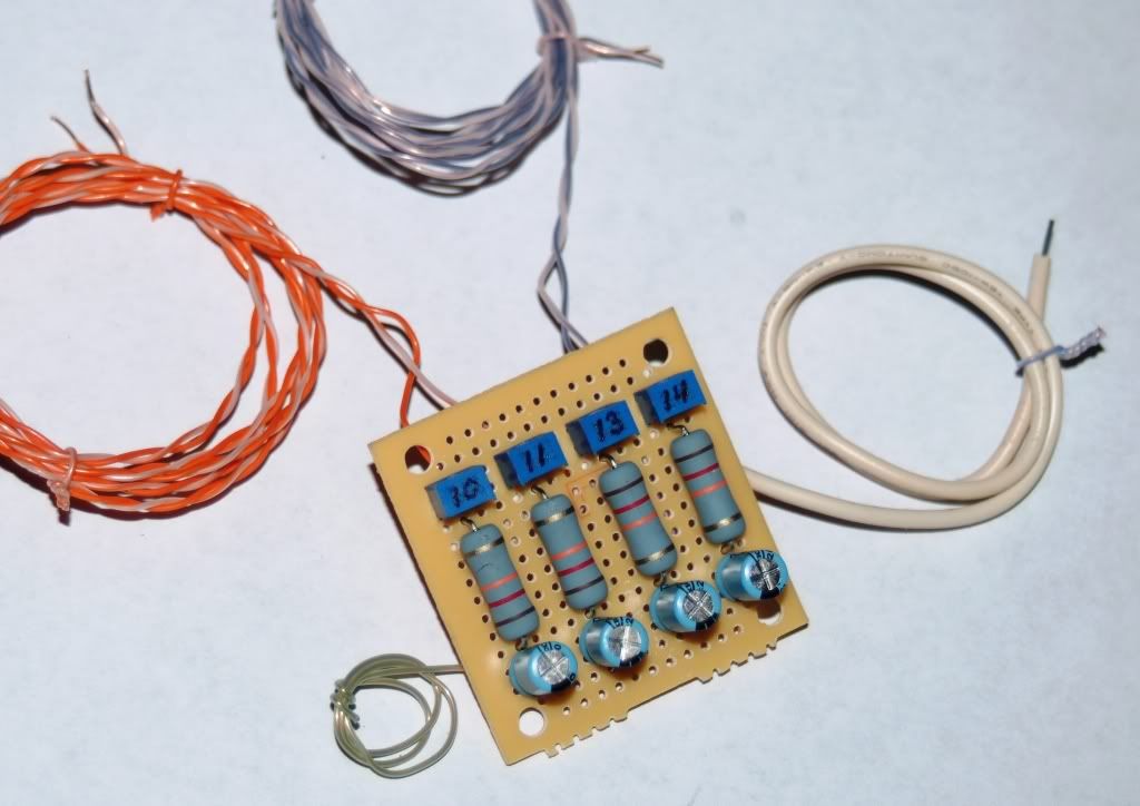
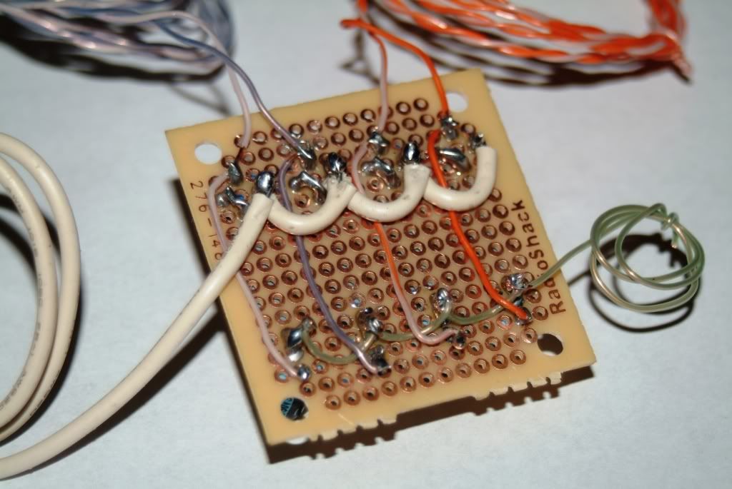
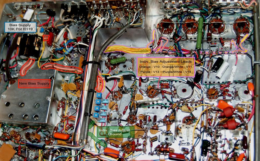
Pictures I got...

...from here. http://www.audiokarma.org/forums/showthread.php?t=373498

IndBiasSupplydiag.jpg


IBPMFront.jpg


IBPMBack.jpg


IBPMinstalled3markedupflat.jpg


Good to see you here again

martin

Hi Guys! :banana:
Just curious before we put this together. Why is the bias line going into terminal "1" on the pot instead of "3"?
Isn't a volume pot wired this way? So that the volume increases with clockwise rotation? Wouldn't it work the opposite way if the bias voltage was fed into "1"?
On volume pots isn't terminal "1" the one that is normally the one to ground?
Please be patient, just trying to understand (and a little nervous about getting this right the first time!)
Thank you all! :yes:
Phyllis
 
It's a simple bipolar pot via pin1 and pin 3. Pin2 is ALWAYS the WIPER. It works both ways.

Doesn't matter which end you put the input on, the output is gonna come out the other side. You just turn it the opposite way. It's a matter of preference. Some of us are left handed and some are right handed. But the writing all comes out the same.

If you prefer a clockwise rotation, put your input on the left. If you prefer a anticlockwise rotation, use the right. There really is no right or wrong way. Like I said it's a matter of preference.

If this were a GOV'T job with a production order and a 25lb specification book, there would be a 3" section on how the pots MUST BE wired up, what type and brand of wire to use and specifications on the wire coating of 5 pages, what solder to use, what soldering iron to use, what heat to use +/-5degrees, what type and how much flux to use, allowable scorch marks in number and size, allowable melting of the
wirecoating at the joints, certfication of the assembler, and currency certifications, just to name a few items. And that would just be from the buyer. Then you get into EPA regs for solder fumes, protective equipment (including respirators), possible hazardous materials, fire protection, Fire suppresion, Community notification in case of an emergency, etc. and with over 100 different agancies weighing in with conflicting and overlapping jurisdictions and regulations, it's a wonder that anything gets done in the Government or FOR the Government!!!!


Larry

Hi Larry! :banana:
So for a clockwise INCREASE wire as shown in the picture?
I only asked as it seems the intuitive way to make voltages go UP with clockwise rotation, like a volume pot is usually wired, and just wanted to make sure.
This drawing is the opposite of that if I am understanding it correctly.
I also understand a little about pots to know that nothing is set in stone! :yes:
With a water faucet it is typically the other way around! (we don't want that :no:) But like you said, there's no rule that says it HAS to be that way.
I feel like you are mocking me a little :tears:
You have to remember that I only started in on this hobby a few months ago.
Everything is not second nature for me like it is for a lot of you guys.
Better to measure twice and cut once!
Just about the time I think I have something down then there is a little twist!
Read a lot of sad horror stories here and just want to avoid one of our own.
Sorry if my question bothered you :no:
Phyllis
 
I wan't mocking you just pointing out that in the world of DIY there are no set rules for how you build it other than making the circuit work. How you do it is up to you, not all the contractor and gov't reg, rules, and gobbledegook that is out there in the real world.

Wire it up as shown for a clockwise increase. Use your meter to doublecheck.

Hi Larry! :banana:
I am sorry if I sounded whiny or anything!
I know there are so many options and that's what makes it hard sometimes to choose and also why all the seemingly redundant questions.
It's a LOT to possess. The Sheldon Stokes board was fairly easy 'cause it was basically like paint by numbers and comes with very specific diagrams.
It's like trying to learn two languages at the same time sometimes, when there are so many ways something can be done.
I just want to be as sure as I can about all the many details! :yes:
That's why you, like some others, have been so valuable and helpful to me through all of this! :yes:
And I THANK YOU! :yes:
Still my friend? :wave:
Phyllis
 
Zero resistance will be the same as a straight line from the bias supply cap to the tube. Which should be the most NEGATIVE voltage, away from the tube. As you turn clockwise you'll go closer to zero volts. But because pins 2 and 3 are tied together (see the lead from the R/C pack off pin 2?) you'll have a 12K backup should the pot short so it WON'T go to ZERO VOLTAGE. You'll have a FULL range from say for example -22V(full anticlockwise) to -12V(full clockwise). With it on the 12K resistor it'll be right around the lowest voltage or a little more(say about -12v) it prevents the shorted pot from allowing a ZERO Voltage situation. It's not intuitive I know, but if you look at it as shotgun bores it'll probably stick better.

To see what I mean do the following.
With a trimmer not connected to anything, turn the knob to the full anticlockwise position. Should be zero ohms or close to it with the meter connected to pins 1 and 2. (This is your straight line voltage as it is out fo the bias cap). Now turn the knob to the full clockwise position. Should be 10K or so, say within 10%. Now add a 12K resistor to pins 2 and 3. with the meter on pins 1 & 2, repeat the above test. The resistance changes up to a point(about 1/2 or 2/3 way) and then steadies out for the rest of the travel. (This is the backup). If the internal components short out, then the 12K resistor takes over and prevents the voltage from going to ZERO! The tube may get overloaded, but it won't melt the circuit, and it may blow the 10oHm cathode resistor shutting it down. So you've got a couple of redundant safeties here.

Kind of like Shotgun bores. The largest bore has the smallest number and the smallest bore has the largest number.

Zero resistance has the largest NEGATIVE Voltage (if your bias supply is -22 then it's -22) where 10K resistance will be the smallest Negative voltage (say about -12V for example). So think of Full Counterclockwise(Zero Resistance) as a 10gauge bore that lets thru a lot of Negative voltage(-22V) and Full clockwise as a 22ga(10K resistance) that restricts the voltage(-12V).

"Clear as Water? Or clear as Mud?" ( Thanks to Sister Jeanne Marie 5th grade 1965-66). If you said Mud, she'd whack you with a ruler on your knuckles!
 
Last edited:
Back
Top Bottom