• The move to the new server is done. There are some software and database maintenance updates in process. This has us passing the hat around to help out. We appreciate any donations. Seriously, even a dollar helps. The payment page may be found here - https://www.audiokarma.org/support.html

Ultimate Marantz Model 7 Restoration Thread

crooner

Tube Marantzed
I have been a fan of the Model 7 preamplifier for almost thirty years now. It was one of the first american vacuum tube Hi-Fi products that appreciated dramatically at the beginning of the 1980's as demand from the far east, specially Japan, often outstripped the supply.

The Model 7, introduced in December 1958, was considered an instant classic with features and design widely copied not only by domestic competitors but also the fledgling Japanese audio industry as well. The McIntosh C11 and C22 were virtually identical copies in circuit and component/chassis layout. The later Audio Research SP-3, a sonic benchmark of the 1970's, also borrowed heavily from it.

Restoring one of these have always been a challenge. Somehow the old parts seem to influence the overall sonic character of the preamp. However, there are other mysteries that I will be uncovering in this thread. A near archaeological research was undertaken to try to learn as much as possible from this design and what affects its sound and overall performance.

Looking at literally hundreds of inner pictures of Model 7's (accumulated from over ten years worth of eBay auctions and my own examples), show all kinds of repairs. From simple recaps using more modern film caps (Orange Drops seemed to be the choice by the 1970s and 80s) to some wild circuit modifications. The original Sprague "bumblebee" or Black Beauty oil impregnated paper caps are often said to become leaky with humidity or cracks in their molded plastic bodies.

In the examples I have owned over the years I have lucked out, as the Bumblebees have performed well with no need for replacement. However, the question of long term longevity always lingered in my mind: after more than 50 years of use, they could be failing at any time now...

Then we have the always controversial question about selenium rectifiers. These were being replaced with silicon as early as the late 1960's as seen in some examples. The rectifiers, like the rest of the parts on these preamps are very conservatively operated. As such they tend to "soften" as they age rather than fail catastrophically. I know of no documented incident in which a selenium has shorted or caused toxic fumes to be released in a Marantz Model 7.

The preamplifier uses two selenium rectifiers. The B+ rectifier is a high voltage low current device in a half wave configuration. A NOS example will output around 300V DC before filtering. Typical rectifiers will soften to around 280V, and this will not affect operation much, if at all. This is because the circuit was designed to produce up to 15V output with very low distortion. The actual power amp drive requirements are just a few volts, typically less than 2V, so a 20 volt drop in B+ is pretty much inconsequential.

The schematic for the Model 7 shows the output from the rectifier to be 328V DC. This was a rather optimistic figure since a stock preamp with a fresh B+ selenium rectifier will barely make it over 300V DC.

The other Selenium rectifier supplying DC voltage to the heaters is a 25V 600 ma bridge. The raw output from the rectifier is 25V, which is then reduced by filtering/voltage divider resistors to around 18V.

I will be performing the restoration on a Model 7 with serial number in the early 19000 range, manufactured in late 1963, early 1964. The preamp is stock with the exception of the heater selenium rectifier which was replaced with a silicon bridge sometime in its life.

For baseline measurements I will be using my reference Model 7 which is a very early unit with serial number in the 10200 range. This preamp has very low noise and distortion and the sound quality from it is nothing short of astonishing. Very lifelike specially with female vocals and woodwinds. Instrument placement is uncanny in 3D fashion. The preamp is completely stock and fitted with ribbed plate diamond bottom Telefunken 12AX7's. All voltages seem to be in spec, except for HV B+ selenium output which hovers around 283V with a line voltage of 117V, which is the design center. Like I mentioned before, this does not seem to affect the preamp's performance in any way.

I will be focusing on trying to, at least, replicate the sonics of my reference preamp by means of modern replacement capacitors, rectifiers and assorted parts. I will also be trying a very high-end stepped attenuator which is probably a first in this type of preamp.

I hope this thread serves a "knowledge base" for this type of restoration where we can learn from years of attempts by others to modify this preamp and add new things that we discover along the way.

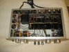
Attached are pictures of my reference unit and the restoration candidate preamp in "as found" condition:
IMG_8297.JPG IMG_0198.JPG
 
Last edited:
Register to hide this ad
The candidate preamp is in overall good shape although it came from a Florida humid environment and has some rust in metal parts such as rivets, brackets and luckily on only a few solder joints in the power supply.

The restoration will involve the following:

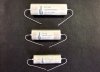
- Signal/Coupling caps will be replaced with Arizona Capacitor "Cactus" caps, as recommended by Mr Shirokazu Yazaki from SPEC Corp and as seen in this blog by fellow enthusiast Nattawut Uamkruea:

http://mellowgroovy.blogspot.com/2016/01/marantz-7c-modify-Real-Sound.html

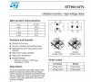
- The high voltage B+ selenium rectifier will be replaced with an industrial grade ultrafast recovery rectifier, the STTH6110TV2. A series resistor will be added to bring DC output voltage down to 300V, which is what a fresh Selenium produces.

- The heater selenium will be replaced with a custom made bridge using On Semi MBR360 Schottky diodes and a snubber circuit comprised of an oil cap and resistor. A series resistor will be added to mimic the selenium voltage output as well.

- The original carbon volume control will be replaced with a custom made 48 step attenuator by Khozmo acoustics. Remote control capability will be added as well.

- The cement wirewound and carbon resistors in the power supply will be replaced with more temperature stable vitreous enamel types in an attempt to prevent voltage sagging without resorting to active regulation.
 

Attachments

  • 1index_r6_c1.jpg
    1index_r6_c1.jpg
    39.9 KB · Views: 559
  • Capture.JPG
    Capture.JPG
    78 KB · Views: 547
  • IMG_0172.JPG
    IMG_0172.JPG
    60.2 KB · Views: 556
  • IMG_0197.JPG
    IMG_0197.JPG
    94.7 KB · Views: 558
  • IMG_0192.JPG
    IMG_0192.JPG
    116.1 KB · Views: 560
  • 10.jpg
    10.jpg
    147.9 KB · Views: 548
Last edited:
MickeySmile, thanks for joining.

I wanted to give this preamp its own character and recognizable appearance. Since it was missing one of the top hat lever covers, I decided to get all white/cream replacements. These are also vintage Daka Ware brand. To complete the new "look" I installed a white slide power switch originally from a solid state Marantz 7T. Physically identical to the stock switch, except for the color...

IMG_0265.jpg IMG_0280.jpg
 
Last edited:
I have a SS 33 and matching 16. I would love to have a 7c! An old freind was one of those sending everything tube from the US to Japan. It was crazy what he was getting for 7's, 10's and also Dynaco stuff back then. Its nice to see another 7 restored. I like the white top hats.
 
I have a SS 33 and matching 16. I would love to have a 7c! An old freind was one of those sending everything tube from the US to Japan. It was crazy what he was getting for 7's, 10's and also Dynaco stuff back then. Its nice to see another 7 restored. I like the white top hats.
Yep. These things are worth so much money nowadays that it was rather excruciating to find the right example at a good price!

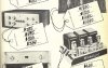
I am attaching some scans from the December 1980 article in High Fidelity magazine that first mentioned the export of these fine units to Japan...
 

Attachments

  • a.JPG
    a.JPG
    93 KB · Views: 269
  • b.JPG
    b.JPG
    113.7 KB · Views: 250
  • c.JPG
    c.JPG
    39.7 KB · Views: 249
  • d.JPG
    d.JPG
    29.6 KB · Views: 230
  • e.JPG
    e.JPG
    118.5 KB · Views: 236
Very interesting choices, I'll bet it certainly will outperform the original. I reconditioned my Consolettes with high temperature nichicons stuffed in the original cans and spraugue vitamin Qs ... On my 7 I did also restuff the cans and used a silicon rectifier for the b+ I got an NOS selenium bridge for the filament supply.


Let us know how things will sound.... this is another 7 in addition to the one you already have?
 
This will be fascinating to watch! No doubt you are aware of a (somewhat) similar effort with a 7C that was presented in the 1981 #1 edition of Audio Amateur magazine? I believe that effort also included B+ regulation as I recall. Conversion to a full wave bridge rectifier will allow for cooler power transformer operation as well.

Dave
 
Very interesting choices, I'll bet it certainly will outperform the original. I reconditioned my Consolettes with high temperature nichicons stuffed in the original cans and spraugue vitamin Qs ... On my 7 I did also restuff the cans and used a silicon rectifier for the b+ I got an NOS selenium bridge for the filament supply.


Let us know how things will sound.... this is another 7 in addition to the one you already have?

Thanks kcin. An honor to have you contribute to this thread. I think the original is as good as it gets in stock form. I always shake my head in disbelief when I listen to my very early example, which is the baseline for these mods, by the way. This preamp is so smooth and noise free. Not to mention the uncanny "3D" like palpability of all the instruments. You can easily hear whispers, and other noises in the venue. And it is also good to single out good recordings from bad ones. With the really great recordings, it's just amazing how the soundstage just expands. I could go on and on...

The thing is, that I have always heard how "updating" or even just recapping the Marantz 7 causes the "magic" to go away. My objective here is to update the preamp, improve it slightly in meaningful areas and yet preserve some of that magic. To this effect, I have compiled all the information possible and I will also benefit from previous attempts, so that I can take the positive and discard the useless "gimmicks" that do nothing to improve the sound. It is a challenge. There is a possibility these modifications may yield a preamp that is excessively detailed and bright. I hope not. I have been careful in my parts choices, so we'll see!

So far the power supply cans appear to be good. I will leave the option of re-stuffing them as the last thing to do after everything else is taken care of.

Did you use a series resistor after the B+ silicon diode? Most folks don't add one. You know why? Because installing a modern diode will produce 330V DC which agrees completely with the voltage shown in the schematic. Research and my experience with at least 5 examples of the Model 7 over the years, tells me this voltage is wrong. It needs to be reduced to at least 300V DC. Most seleniums, specially well used ones, produce even less voltage. So if part of the "magic" resides in the selenium rectifier, the output voltage needs to be seriously considered. I found that when I replaced the B+ selenium with silicon and no series resistor, the sound became harder and less engaging. Perhaps this drives the tubes more towards the edge and away from their sweet spot. Remember, this thing already has tremendous gain by design.

Saul designed these preamps to output 15V, so that way it would be coasting at 1V or so, which is the voltage required to drive the matching Marantz tube power amp to full output. So a higher B+ is not necessarily going to improve performance, and judging by my listening impressions, it may just be the opposite!
 
Last edited:
This will be fascinating to watch! No doubt you are aware of a (somewhat) similar effort with a 7C that was presented in the 1981 #1 edition of Audio Amateur magazine? I believe that effort also included B+ regulation as I recall. Conversion to a full wave bridge rectifier will allow for cooler power transformer operation as well.

Dave
Hi Dave, what an honor to have you contribute to this thread as well.

Yes, I researched that article. It was the first well documented modification of the Model 7, and actually inspired Sid Smith to offer his own mods in the mid 1980's.
Walt Jung had just released his "picking capacitors" article in Audio Magazine and poly caps were all the rage then. So it was a natural they were included in this modification.
Unfortunately, poly caps and the Marantz 7 don't seem to get along very well (they tend to sound "bright") so in recent years they have fallen out of favor not just for recapping this piece but other vintage restorations as well. Ditto for Metal Film Resistors.

The regulated power supply was a radical modification.Like AK'er Kcin mentioned in another thread a few years back, the regulator used was very primitive and again the benefits claimed proved to be detrimental. I don't think power supply voltage fluctuations are an issue with this design. As the folks at SPEC corporation in Japan have discovered, it is drifting carbon voltage dividing resistors that cause most of the issues. So the design is sound. Better parts in these areas should yield improvements without radically changing the sound, or so we hope...

As for the half wave rectification in the B+ circuit, I have indeed noticed the power transformer gets a little warm after 3 or more hours of operation. So in that regard, the full wave modification was an improvement.

The appearance in the market of the Arizona "Cactus" caps was the main motivator to go ahead with this project. These caps are mylar and Paper in Oil, and offer the benefits of both. Apparently, many folks in Japan are very happy with their recapped Model 7's, claiming the original sonic signature has been preserved with added resolution as well.
 
Last edited:
My own experience is that other than to stabilize output stage operation (where their benefits can be significant if correctly applied), the use of B+ regulators -- of frankly any type -- tends to produce a very sterile, un-involving sound that I quickly tire of. All stages preceding the output stage operate purely in class A anyway, so there is virtually zero variation in current draw to need a regulator for to begin with for those stages. About the only thing a B+ regulator will do in a preamp is to stabilize the B+ against changes in AC line voltage. To that point, most Class A stages are rather insensitive to minor changes in B+ voltage, with the biggest effect being on the amount of undistorted output that's available as B+ voltages drop.

Dave
 
Speaking of modifications, I am attaching some I have seen over the years. Many are over the top, and downright crazy!
 

Attachments

  • serial 13094 side angle.jpg
    serial 13094 side angle.jpg
    354.2 KB · Views: 431
  • serial 18128 detail.JPG
    serial 18128 detail.JPG
    31.7 KB · Views: 403
  • serial 18128 with external PS.JPG
    serial 18128 with external PS.JPG
    18.8 KB · Views: 362
  • P1010422w.jpg
    P1010422w.jpg
    145.4 KB · Views: 407
  • kludged marantz 7.jpg
    kludged marantz 7.jpg
    47 KB · Views: 379
  • s-l1600.jpg
    s-l1600.jpg
    119.8 KB · Views: 393
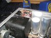
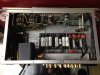
Back to my restoration, attached are pics of the B+ and Heater rectifier circuits. I built the heater bridge and snubber on a turret board to match the original Marantz construction:

IMG_0314.JPG IMG_0289.jpg
 
Last edited:
Crooner,

I cant wait for your impressions on sound at the conclusion of your restore.

I have been anticipating the results of your modifications since you mentioned trying the cactus caps in the other thread. I'm so happy that they are available now and that it may be possible to upgrade the Marantz seven without compromising its signature sound.

I too have a bone stock 7 with Telefunken 12AX7's. While it meets factory specs, I do worry about its age but have been reluctant to send it out for restoration due to concerns about changing the sound. However, your research regarding existing rectification and your planned modifications do ease my mind.

Thank you for sharing your experience and progress!

I'll be anxiously watching and awaiting your findings.

Cheers,
Uenjoy
 
Last edited:
Crooner,

I cant wait for your impressions on sound at the conclusion of your restore.

I have been anticipating the results of your modifications since you mentioned trying the cactus caps in the other thread. I'm so happy that they are available now and that it may be possible to upgrade the Marantz seven without compromising its signature sound.

I too have a bone stock 7 with Telefunken 12AX7's. While it meets factory specs, I do worry about its age but have been reluctant to send it out for restoration due to concerns about changing the sound. However, your research regarding existing rectification and your planned modifications do ease my mind.

Thank you for sharing your experience and progress!

I'll be anxiously watching and awaiting your findings.

Cheers,
Uenjoy

Uenjoy, thanks for the kind words. Now comes the rather daunting task of desoldering all the old caps. I will take my time to make sure all the joints are done correctly. Some of the connections, specially those going to the tube sockets are specially challenging as they are so closely spaced. My eyesight isn't what it used to be!
 
Boy!! You look inside that thing and wonder if there is any HUM with all the wireing going everywhich way.
But I gess Ole' Saul knew what he was doing.
 
Boy!! You look inside that thing and wonder if there is any HUM with all the wireing going everywhich way.
But I gess Ole' Saul knew what he was doing.
Yes. There are little tricks here and there to prevent hum. Critical cabling is shielded and sometimes an extra ground braid is used. Disturbing the wire dress can introduce hum also.
 
Fantastic ! as I planify to DIY one someday, when my electronic skills will be good enough, to join my 8B and 10B.

It's been 4 years that I search around the Model 7, collecting photos, datas and articles on it.

The model 7 is, for me, the ultimate preamp, a masterpiece sonically, estihetically, functionnaly and reliability. It is a masterpiece of design.

I recently listen to it on an very high end, high efficiency system (105 dB/1w/1m), only the volume control was change by an english replica, and it was fabulous.

I will be plainly satisfied by the original circuits, but I am curious of what moods can be done to improove it. I originnaly plan to made two prototype, one completely original, the other mooded.

The only concern with the seven is that the bass when down around 70 Hz to prevent rumble.

The only moods that I considered valid were those done by the original designer, Sid Smith.

His focus was on :

- removing the electrolytics couplings caps in the phono feedback;
- disconnect tone, filter, tape switch for a more direct path;
- changing Telefunken ECC83 by ECC803S to lower the noise floor;
- Increase the wire isolation in the phono section;
- update de power supply for better regulations;
- Increase the coupling cap value;
- Polypropylene new coupling cap (Sprague 730P) and some Sprague Orange Drop and, if I not mistaking, few polystyrene cap.
- Metal resistors;
- Golden plated teflon insulated jacks.
- Trim the value of resistors in the phonostage to have the less variation and a more precise RIAA curves;

Now we know that metal resistors can make the sound hard. So we can discards the material change.

Keep in mind that at that time, M.Smith were not aware of subjectives differences between passive parts.

Heres the Sid Smith moods and picture of modify samples. Since you already seen (and critics) the samples on hifi heroin, here is a neater one :


file.php.jpg SID SMITH modification 1.jpg SID SMITH modification 2.jpg
Marantz 7 modifications 2.JPG
Marantz 7 modifications 3.JPG
Marantz 7 modifications 4.JPG
Marantz 7 modifications 5.JPG
 
Back
Top Bottom