• The move to the new server is done. There are some software and database maintenance updates in process. This has us passing the hat around to help out. We appreciate any donations. Seriously, even a dollar helps. The payment page may be found here - https://www.audiokarma.org/support.html

Ultimate Marantz Model 7 Restoration Thread

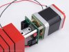
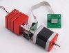
By the way, my Khozmo 48 step remote controlled attenuator just shipped from Warsaw, Poland!
Can't wait until it gets here. The motor and electronics feed from a 8 to 15V DC power source. I am thinking about tapping from the heater supply.
The remote control IR sensor will go in the pilot light opening, thus preventing drilling holes. I am hoping it can coexist with the #49 lamp.

Speaking of the pilot lamp, I may replace it with a warm white LED to reduce the load a bit on the power transformer...

1index_r6_c1.jpg
 
Nice work I have a work bench and I always tend to stand and not sit... so if it works!.. are you going to have enough space for the remote volume control?.. looks large.
 
I took some measurements and apparently it will fit. It will extend towards the back but the turret board sits low enough not to be a problem.
I was more concerned about the weight and that it may need some kind of support at the back. Apparently it's all made of CNC machined aluminum, so it shouldn't be too heavy. We'll see...
The version I got is in silver, not red. I don't really need the LED display, so I will hide it somewhere. Khozmo is sending an extra IR sensor and cable so that I can position it at the pilot light opening.

I am hoping that tapping from the 18V to the heaters does not cause noise or pops when the motor is actuated. If so, I'll need some kind of isolation or a regulator board of some kind. I may just end up using a wall wart plugged into one of the convenience outlets if necessary.
8688_selecteur_shunt_10k_remote_2.jpg 8688_selecteur_shunt_10k_remote_4.jpg
 
Last edited:
I just wanted to say that it is a pleasure reading this thread! Thank you! ..........and about the work bench: pshaw! Our dining table has soldering iron burn marks on it, my wife said she wanted a new table, for her birthday last month- she received an antique table cloth and was very happy. The household scars resulting from our passion for audio is evidence of our dedication.... and healthy insanity... Be proud!
 
I took some measurements and apparently it will fit. It will extend towards the back but the turret board sits low enough not to be a problem.
I was more concerned about the weight and that it may need some kind of support at the back. Apparently it's all made of CNC machined aluminum, so it shouldn't be too heavy. We'll see...
The version I got is in silver, not red. I don't really need the LED display, so I will hide it somewhere. Khozmo is sending an extra IR sensor and cable so that I can position it at the pilot light opening.

I am hoping that tapping from the 18V to the heaters does not cause noise or pops when the motor is actuated. If so, I'll need some kind of isolation or a regulator board of some kind. I may just end up using a wall wart plugged into one of the convenience outlets if necessary.
View attachment 774026 View attachment 774027

You may in fact find that you need some sort of support... I think that the wall wart idea is a good one also. Looking forward to seeing it come together.
 
You may be able to just disconnect the LED board? I would love to hear it when your finished.

That's what I thought, but Khozmo says the board is needed for the remote to work. Space is really tight inside the preamp so I am going to have to be creative.
I am thinking about fabricating new top and bottom panels out of plexiglass or acrylic with perforated holes like the originals. Hopefully shielding from from RFI or EMI won't be an issue. I could mount the little board on the see through clear top so that the LED numbers can be seen. And since it has a flat cable, it can be disconnected when the top of the preamp is removed. I don't know if the extra cable with IR sensor is attached to the board on the attenuator or the LED board.

I may relocate the IR sensor to an external box outside the preamp....
 
Last edited:
Painting the underside of the plexi black except for the small square for the readout would look cool.
 
Painting the underside of the plexi black except for the small square for the readout would look cool.

Yes definitely. Or black out certain areas only. The opposite would be also be cool. enclosing the little board in an opaque/smoked enclosure that would only show the display when lit, hiding everything else from view....
 
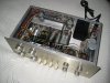
Almost done recapping. I am missing the two 0.47 uF caps in the phono section which will be arriving next week...

akl1.JPG
akl2.JPG
 
Very nice clean work! Will you be replacing any resistors other than those out of spec?

Thank you, I am taking my sweet time with this one, obsessing about all the little details. I guess it is also benefiting from years of experience soldering and desoldering. I had to learn how to do it cleanly, after butchering many a dynaco and heathkit :D

I like the sound of the old carbons and the mil spec carbon film resistors are nice also. I checked against my other Marantz 7, and they measure very close in circuit. I will double check again after I am done recapping to make sure heat from soldering iron didn't make them drift. Of course, they could drift with temperature while operating. We'll see...

The power supply carbons will definitely get replaced with vitreous enamel, more stable and this is critical for proper regulation...
 
Last edited:
Although heretical, I wonder how the Marantz 7 would look with a new TMZ2 black laser etched faceplate with anodized or polished silver knobs, and maybe red or blue Dakaware switch covers? Just as an alternate look.

The wall wart idea is probably the most expedient, but if there was room, I'd rather have a small circuit board with an on-board transformer and regulated power supply, instead of hanging the wart off the back. But there may not be any room.

I notice the contacts on the stepped attenuator are open and exposed, although gold plated. Wonder if you should consider placed either plastic or metal around to shield and protect? Definitely need a shot of DeOxit and then Pro or Gold to preserve.

I have been researching power supplies and there are some tiny ones made in China that may work. Some are DC to DC bucking types, which would reduce the 25V raw output from heater rectifier to 12V regulated DC. Others would take 115V AC and using a switch mode PS, produce 12V DC. In any case, I would enclose the board in a black plastic case and perhaps epoxy it to the bottom of the power transformer as there is some space down there. Hoping the switcher inside these supplies don't generate any noise in the preamp's output....

Excellent point on the exposed contacts. I will contact Khozmo for ideas on how to prevent contaminants from getting inside.
 
Yes, noise would be the one issue with any switching supply that I would worry about, especially if one is using phono inputs. A good small brute force linear regulator, if in a small enough package, might be a decent choice - small toroid or E-L transformer, small full wave bridge, linear 3 pin regulator, two electrolytic caps with poly bypasses, and one reverse protection diode would do it.
 
Here's a tiny one that looks ideal:

If it gives you sufficient current, that looks like it could mount easily on a nice board (don't use perfboard since you can use some screwdown terminals for connections) hardwired
 
Last edited:
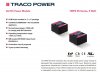
Traco Power, a Swiss company, makes some nice AC-DC encapsulated modules that are much higher quality and have low EMI/RFI radiation. The switching frequency is 65 kHz, PWM:

Capture.JPG
 
Last edited:
Back
Top Bottom