Yes, i can share the model I habe made in LTspice for the output transformer. It is probably improvable.
Here the content of the file :
******************
.SUBCKT VDV-1070-UC A1 B A2 K2 M2 M1 K1 S1 S2 FB1 FB2
* PLITRON VDV-1070-UC OUTPUT TRANSFORMER 4KOHM UC PRIMARY
* OL NUMBERS CORRESPOND TO TRANSFORMER SCHEMATIC.
.PARAM PRIML=1768 ; TOTAL PRIMARY L (FROM SPECS).
.PARAM LRATIO={5/4000} ; INDUCTANCE RATIO: (5 OHMS)/(PRIMARY).
.PARAM QFCTR=1821000 ; Q-FACTOR: PRIMARY SHUNT L/LEAKAGE L.
LP1 A1 B {PRIML*.0625} ; PRIMARY
LP2 B A2 {PRIML*.0625}
LP3 K2 M2 {PRIML*.0625}
LP4 M1 K1 {PRIML*.0625}
CP1 A1 A2 .1745NF ; CAPACITANCE FROM SPECS SPREAD ON ALL TAPS
CP2 K2 M2 .087NF;
CP3 M1 K1 .087NF;
LP5 S1 S2 {PRIML*LRATIO} ; SPEAKER SECONDARY
LP6 FB1 FB2 {PRIML*LRATIO} ; FEEDBACK WINDING
K1 LP1 LP2 .9999989 ;
K2 LP1 LP3 1 ;unity coupled
K3 LP1 LP4 .9999989 ;
K4 LP1 LP5 .9999989 ;
K5 LP1 LP6 .9999989;
K6 LP2 LP3 .9999989 ;
K7 LP2 LP4 1 ;Unity coupled
K8 LP2 LP5 .9999989 ;
K9 LP2 LP6 .9999989 ;
K10 LP3 LP4 .9999989;
K11 LP3 LP5 .9999989 ;
K12 LP3 LP6 .9999989 ;
K13 LP4 LP5 .9999989 ;
K14 LP4 LP6 .9999989 ;
K15 LP5 LP6 .9999989;
.ENDS VDV-1070-UC
The schematic logic is explained below :
A1 : connected to anode 1
B: connected to + HT
A2 connected to anode 2
K2 : to cathode 2
M2 : ground
M1 : ground
K1 : cathode 1
S1 : Speaker 1
S2 : speaker 2
FB 1 : Feedback 1
FB 2 : Feedback 2
Here a screenshot :
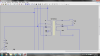
I show the symbol. It is not very nice, but you just have to write VDV-1070-UC in the filed value for having the right calculation (obvioulsy, record the file above in a .txt and make the right LT spice directive : .INC yourfile.txt). I have not succeed for uploading the .sym. You have ti draw it again.
Some comments :
- I have spread the capacitance on the different taps.
- The winding resistance of the winding are not included in the model. You have to add it manually on the scheme (I have measured : A1-B : 19.6 ohm, B-A2 : 21.7 ohms, K2 M2 : 19,6 ohms and K1 M1 : 21,7 ohms)
- I have assumed a coupling ratio of 1 for the unity coupled windings and try to spread the inductance leakage on other windings.
Hope it helps you. It is a first step which is not perfectly matching with my measures (for the ringing)



 Today it works properly. (I had a comment on my previous post : the choice 1 works if the tap 4+5 and 6+7 are crossed.). .