• The move to the new server is done. There are some software and database maintenance updates in process. This has us passing the hat around to help out. We appreciate any donations. Seriously, even a dollar helps. The payment page may be found here - https://www.audiokarma.org/support.html

unusual power amplifier - DC offset etc

audiogymp

Active Member
Hi

I'd appreciate some suggestions on an amp I'm working on. Works well, sounds good but there's some DC offset and no manual or schematics available.

Background: The amp is made by an Australian business called Audio Assemblers Pty Ltd. Some of their stuff is reputed to be PA-grade but there is also stuff that is well regarded. The amp in question (I am told) came out of a cinema and it appears to have been custom built for that application. Looks well built. It sounded horrible with sources through the balanced inputs (both unbalanced and unbalanced converted to balanced). But recently I decided to try bypassing the the input circuit and built a basic input and injected the signal straight into the amp board. Bingo. Sounds good on expendable bench speakers but there's DC offset and I am cautions about running it into better speakers. DC offset 70/30 mV.

The circuit board has the part no. FMC 2609 but I doubt there is anyone out there with actual knowledge or documentation.

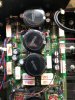
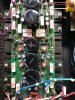
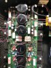
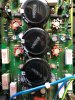
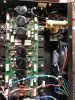
I've included some photos in the hope that they may be of some assistance.

There are 4 10K trim pots. two of them are near the LM3916N chips and I suspect that they are for setting the level for either the clipping indicators or the single LED for each channel that light when the output hits a particular level.

The other two trim pots are around the four transistors on the PCB with the red heat sinks. I suspect that these are for adjusting idling parameters. I am cautious about messing about with them in the absence of any marked testing points (the only options that occur to me are the R51 resistors that appear to be emitter resistors).

In the absence of any specific info about the amp, the following questions come to mind.
1. Is there some kind of standard approach to adjusting a power stage you know nothing about?
2. 70mV gives a power dissipation of about 1 mW into 6 Ohms. It appears to be far from ideal but is it something to be concerned about? (I would be using the amp with an outboard speaker protection device that opens at 1.5V DC)

Cheers
 

Attachments
  • IMG_1219.jpeg
    IMG_1219.jpeg
    176.5 KB · Views: 61
  • IMG_1220.jpeg
    IMG_1220.jpeg
    145.2 KB · Views: 55
  • IMG_1221.jpeg
    IMG_1221.jpeg
    179.4 KB · Views: 54
  • IMG_1222.jpeg
    IMG_1222.jpeg
    168.7 KB · Views: 57
  • IMG_1223.jpeg
    IMG_1223.jpeg
    159.8 KB · Views: 53
Last edited:
Register to hide this ad
It looks like this thread is destined to finish the way it started.

I decided to trust my power calculation and listen to the amp properly. It's connected to my Vandersteens, which it drives with ease. There is no audible difference between the channel with the 30 and the 70mV offset.

This is one of a handful of experiences that remind me how much the perception of volume can come from auditory cues of compression and the labour of the power stage. It is easy to go quite loud with this amp and not know until stepping out of the house and realising that it's at neighbour-bothering volume.

I'd like to set the amp up properly but it's hard to justify messing about with something that sounds this good.
 
While 30mv isn't horrible, it is kind of high. The 70mv on the other channel wouldn't make me happy. The mod done with those bare copper wires just hanging there is a bit spooky. From the picture ot looks like they are touching that one big filter cap. Maybe they are enamel coated? If you measured the DC offset and got the readings you did, you should be able to keep a meter on it and adjust the DC offset if those trimmers are for offset.
I have run into amplifier sections that just had trimmers to adjust the voltage for each channel using fixed compoants like resistors to set the bias and DC offset. Most direct coupled amps I've worked on had a set of trimmers for bias and DC offset.
 
Thanks for the reply.

The copper wires are insulated and are actually not that close to each other (although it looks that way in the photo).

The input into the amp board is two points for each channel. The original input into the amp board (from the input circuit) was a hot wire and screen wire for each channel. When I first tried injecting into the amp board, I used output from a preamp straight into the amp board (hot/screen respectively). I noticed in this configuration that there was 4.5V between the screen and ground (both the ground on the power amp and the ground connector on the preamp). I grounded the screen line (both to preamp and to power amp, alternatively) and it made no difference to anything. With the input I have wired, the formerly screen wire is now grounded against the power amp. I am fairly certain that I am not injecting DC into the power amp. The input may look a bit hap-hazard but it is an arrangement intended to minimise capacitance and cross-talk (the solid core wires are pretty good at staying where intended).

One point worth mentioning is that the DC offset is the same whether speakers are connected or not. This is something I find surprising. But it leads me to think that the offset may be set and driven by the amp circuit. I have observed the same thing with two preamps connected to this power amp.

It had occurred to me to set a meter on the DC offset and also across an emitter resistor and see what happens if I turn one of the trim pots. It may be the answer. But if I don't get a reading, I have changed something that I don't know how to reset. Hmmm.
 
Last edited:
IMO people get way too worked up over small DC offsets; we're talking millivolts! I've seen amplifiers that specified acceptable offset as <250mV.

I wouldn't mess with it.
 
Thanks for the input, RossW.

It appears that the DC power dissipation of about 1mW by the speakers (mostly the bass drivers) will be small relative to their power handling. The speakers may be displaced from their normal resting position by a degree, which could produce some asymmetry to incursion/excursion. But as noted, I can't hear a difference between 30 and 70mV offset.

If 30/70mV offset don't raise red flags, Im inclined to leave well enough alone. Even at 250mV offset, the DC plower dissipation into 6 Ohm is only about 10mW. It seems that speakers should be able to accomodate this easily, unless there is something I'm missing.

Cheers.
 
dc offset adjustment pots are generally next to the input side of things .the idle current ones being near the outputs .
i would first check the idle current just in case . then adjust one pot and see what changes . 70mv isnt really bad but if it can be adjusted lower it will be better . saying that there is always a risk of things blowing up regardless .
 
I got a habit of doing first round of adjustment under DBT with low wattage bulb. Readings will be lower but it tells me what to expect right out of the wall.
 
I got a habit of doing first round of adjustment under DBT with low wattage bulb. Readings will be lower but it tells me what to expect right out of the wall.
always a good plan to limit the supply current when testing .when unless we are talking jfets
 
The output devices are silicon bipolar 21193/21194 (MJ- prefix from memory). I don't know if there are JFETS up the chain.

It is hard to judge the proximity of the trim pots to the input/output because of the layout of the board. The power in and the outputs are at the bottom of the first photo (as you see it on the screen). There is no adjustment near there. The input is near the middle of the board and there are two trim pots that are reasonably close by. I suspect these may adjust some idling parameter. However, the outputs are arranged around the whole board (one pair on opposite sides of each of the large caps). This makes it difficult to judge the signal path without a schematic or an experienced eye.

If the trim pots adjust bias or offset, I can measure that and at least restore the settings. I am aware that some amps have no adjustment for bias or offset and some only for bias. But are there other possibilities that I may not know how to measure? This could leave me going backwards if a change something I don't know how to re-set.

Also, what do you think about what I speculated in the OP that the two trim pots near the LM3916N chips may be for setting the level for either the clipping indicators or the single LED for each channel that light when the output hits a particular level?
 
Some early SS Rodgers organ amplifiers had "hum adjust" and "bias (balance I think)" trimmers. No idea where to measure that without any schematics found.
 
Also, what do you think about what I speculated in the OP that the two trim pots near the LM3916N chips may be for setting the level for either the clipping indicators or the single LED for each channel that light when the output hits a particular level?
the chip being a display driver i guess you could be right there
 
the other pots look like they could be for bias ..its hard to say for sure especially being a double sided board .
 
I suspect the amp was made in the 90's, maybe a bit later - unlikely to have features that are a throw back to earlier times.

I think your answers are helping but perhaps I could clarify what I'm trying to understand. In the amps I have worked on, the trim pots I can remember have been either for bias, quiescent current or offset (unless they are for something like display level, etc). I'm wondering if there are other amp designs that use trim pots for adjusting some kind of operating voltage or current within the circuit that is different to bias or offset. Am I overthinking this and imagining possibilities that are non-existent or extremely rare?
 
Cap coupled amps have bias and center voltage trimmers. Those are to adjust supply 1/2 of rail voltage to one of the output transistors. Best done with the scope watching positive and negative sine swings and to adjust for symmetrical clipping point.
 
Can you take and record trimpot measurements as they are now? It would give you points to go back to. Then try to attempt adjustment watching both, current across emoter resistors and DC offset. I’d do that with DBT protection just in case those trimmers are doing something else. Bulb glow will tell you if you’re going the wrong way.
 
That's not a bad idea. It'll be tricky getting access to points to measure the resistance from the trim pots unless the upper side of the circuit board reveals alternative connections but it's worth a try.
 
I usually spray contact cleaner into trimmers before I move them. If wiper loses contact, output stage goes into full conduct like in some Pioneer designs. Use bulb small enough to show slight glow before adjusting.
Beware that voltages will be lower with DBT and you’ll have to readjust powered from outlet. Good luck!
 
OK

The trim pots near the middle of the board are for bias and don't appear to affect offset. The trim pots near the LM3916N chips affect neither bias nor offset (and are probably for the level at which the LEDs on the face plate light up).

Looks like I'm going to have to live with the offset. But the bias on the the sides was not the same 9.5 and 4.9mV across half an Ohm, so one side idles at nearly 20mA and the other side at about 10mA.

So, one last question before I drop the hood and go back to listening. Any thoughts on what I should set the bias current at?

PS - the amp develops only modest warmth with current bias.
 
Last edited:
Bias specs are developed by designers based on the crossover distortion analysis during R & D. Then they convert measured current into mA measured across emitter resistors.
If you have oscilloscope, you can do what @Watthour suggested here:

"IF you have an oscilloscope at your disposal, and IF you had a source for a sine wave, you could inject the sine and measure the output with a speaker/load connected, all while monitoring the output with the 'scope. Turn down the bias until the waveform at zero crossover begins to show a null (flat) point in the wave, then turn the bias up until the null is gone. Disconnect the input sine, measure the bias current, and increase that by about 10% for a safety margin.

My guess is that you have everything you need to adjust it, and if not, the sine wave can be played through a CD using a test disc. Incidentally, if you can burn a CD you can download an Audio Test CD file and create your test disc. The ISO disc image file is here:
www.wwdsltd.com/files/AudioTestCDImage.iso

The disc directory is also available:
www.wwdsltd.com/files/AudioDiagnosticTestCDKey.xls"

Complete thread with this and other references is here:

https://audiokarma.org/forums/index...ting—anyone-know-how-to.937024/#post-14277202

I hope this helps!
 
Back
Top Bottom