
• The move to the new server is done. There are some software and database maintenance updates in process. This has us passing the hat around to help out. We appreciate any donations. Seriously, even a dollar helps. The payment page may be found here - https://www.audiokarma.org/support.html

Upgrading Vintage Marantz 1030 Power Supply to Zener Transistor

benhodgson

New Member
Hi,

First time poster.

I've started cleaning up and recapping a Marantz 1030 as a summer project. It's going well. However, one of the things I'd like to do - due to its relative ease - is upgrade the power supply to a better level of regulation. To do this I'm going to replace the resistor to base of the transistor with a zener diode. I first saw this idea (and the fact that no PCB modifications) on a post by Ecluser about a similar power supply on a Marantz 2220.

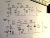
Attached is a schematic of what's current and what's proposed. However, this is where I'm getting lost. I'm trying to calculate what resistor values and wattages I need but just can't get it right. Can anyone help?

The transistor is going from a 2SC1213 to a KSC2383Y as I understand this is a good swap. The electrolytics are all being replaced with new Silmic II ones. The zener diode is 1N5258B, a 36v, 0.5W diode.

Also, can someone tell me if R801 and R804 in the attached image need changing? I'm assuming not and its just to adjust the current the transistor sees?

Thank you in advance for any help,

Ben
IMG_7961.JPG
 
Last edited:
Register to hide this ad
Ok, So I think I may have worked this out. R801 and R804 can stay as-is. R802 can be 600ohm for 10mA across the zener which will mean it runs at 0.36W or it can be a 1k ohm for 6mA and 0.216W. Given the zener data sheet says test current is 1.7mA to 20mA it makes sense to run it a bit cooler. A 0.25W resistor is plenty for either application.

Am I missing anything? Can I keep R801 and R804 as-is?

Thanks
 
I've restored a 1030 and two 1060's and haven't had any problems with the power supply in the factory setup. I replaced the cc resistors with cm ' s, a new transistor, diodes, caps andcalled it good. The one thing that should be changed are the 458 transistors on the line stage and phono boards. They are known for becoming hissy sounding. Use modern replacements.
I haven't heard about what you want to do. Hopefully someone will chime in. Inquiring minds want to know! :D
 
I've restored a 1030 and two 1060's and haven't had any problems with the power supply in the factory setup. I replaced the cc resistors with cm ' s, a new transistor, diodes, caps andcalled it good. The one thing that should be changed are the 458 transistors on the line stage and phono boards. They are known for becoming hissy sounding. Use modern replacements.
I haven't heard about what you want to do. Hopefully someone will chime in. Inquiring minds want to know! :D

Thanks. I've got a whole bunch of KSC1845FTA for just that job. Although, I'll confess, I'm unlikely to do the phono stage as personally I'll only use it once in a blue moon. As I understand it the phono stage board is bypassed for all other inputs.

The 1k is in for R802 and the zener is subbed in for R803. We'll see... if I don't hear any more i may have to risk some live testing.
 
Am I missing anything? Can I keep R801 and R804 as-is?
The thing you're missing is that you don't have enough headroom between the desired output voltage and raw supply voltage to insure reasonably constant Zener bias current. Line regulation and Zener tolerance issues make this a no-go.
 
The thing you're missing is that you don't have enough headroom between the desired output voltage and raw supply voltage to insure reasonably constant Zener bias current. Line regulation and Zener tolerance issues make this a no-go.

Out of interest, why? The 1N5258 is tested and stated on the spec sheets as providing a stable voltage at 1.7mA and I'dbe providing 6mA which seems plenty then.
 
Let's look at it this way: If you allow ±15% raw supply tolerance and ±5% Zener diode tolerance, then you've exceeded your 6V of nominal headroom without even considering raw supply ripple. Zener voltage has a small dependency on operating current as well, but I shouldn't have emphasized this issue.
 
Let's calculate. for a 1/2W zener diode 36V, max current is 0.5W/36V=13.8mA. So this is your upper limit. The transistor is going to need base current ( very important). So I would want say 10mA through R802. This is to ensure I have enough current to keep the zener happy and have capability to provide base current for the transistor.

The raw voltage is 42V, the zener is 36V. So voltage drop across R802 is 42-36=6V. I want 10mA through R802, so the value of R802=6V/10mA=600ohm. This is not a common value, so let's try a common value, 560ohm. Going through the same calculation, 6V/560=10.7mA. I would say this is a good value. You can also try 680ohm, that will give current of 6V/680=8.8mA. This is acceptable also. Make sure you use 1/2W resistor.

Now look at R801. THis is basically a current limiting resistor. Based on the value of R804 and 805, this is not a high current regulator. Stay with the original 47ohm is fine.

Hope this help going through the calculation step by step.
 
Inquiring minds want to know! :D

Inquire no longer. The restorations/modifications to the amp are finished.

  • Power Amp Board - complete recap of all electrolytic caps with SILMIC II
  • Preamp Board - complete recap of all electrolytic caps with SILMIC II and all 6 of the 458 BJTs replaced with KSC1845FTA
  • Power Supply Board
    • recap of all electrolytic caps with SILMIC II (C803-806)
    • C801-802 ceramics replaced with PP
    • R802 replaced with 1k Ohm (its what I had to hand)
    • R803 replaced with a 36v 0.5W zener diode (Vishay 1N5258B-TAP). This is the proposed schematic I posted above.
    • The 47R and 470R were left as-is.

Its sounding great and I'm really, really pleased with it. Sounding a lot better than before. I will replace the 1k resistor with a 1W 560R soon just for longevity's sake (probably when I fine tune the bias) but for now its sounding really good and I'm very, very pleased with it. To my ears (and others) the sound quality has improved considerably. How much of that I can attribute to which changes I don't know (I suspect replacing the 458s made a big difference) but suffice to say I'm really happy with the amp.

EDIT: Worth saying as well. I was going to replace the 3 main chassis-mounted caps (C003-005, which the manual lists as 2*2200uF and 1*3000uF but my amp was 2*2200 and a 4700) with Nichicon Super Throughs however when I tested these they were well within working parameters (unlike a lot of the other electrolytics) and nice Black-Neg caps so I left them as-is hoping this would retain more of the amps original sound.
 
Last edited:
I used a Super Through and two Gold Tunes for the filter and coupling caps. Once done these little amps do sound nice. Even the smallest Marantz offerings back then were made with the same quality parts and construction of the day. Is yours the early model, with main in and pre out jacks? If so the 1030 can make for a nice preamp as well. Mine was the later model without them. I just added them myself. My daughter has my 1030 now. I had two 1060's and gave one to my son when I was finished going through them. If you get the chance to snag a 1060 they are really very nice sounding after some freshening up. Enjoy the 1030! I did.
 
Inquire no longer. The restorations/modifications to the amp are finished.

  • Power Amp Board - complete recap of all electrolytic caps with SILMIC II
  • Preamp Board - complete recap of all electrolytic caps with SILMIC II and all 6 of the 458 BJTs replaced with KSC1845FTA
  • Power Supply Board
    • recap of all electrolytic caps with SILMIC II (C803-806)
    • C801-802 ceramics replaced with PP
    • R802 replaced with 1k Ohm (its what I had to hand)
    • R803 replaced with a 36v 0.5W zener diode (Vishay 1N5258B-TAP). This is the proposed schematic I posted above.
    • The 47R and 470R were left as-is.

Its sounding great and I'm really, really pleased with it. Sounding a lot better than before. I will replace the 1k resistor with a 1W 560R soon just for longevity's sake (probably when I fine tune the bias) but for now its sounding really good and I'm very, very pleased with it. To my ears (and others) the sound quality has improved considerably. How much of that I can attribute to which changes I don't know (I suspect replacing the 458s made a big difference) but suffice to say I'm really happy with the amp.

EDIT: Worth saying as well. I was going to replace the 3 main chassis-mounted caps (C003-005, which the manual lists as 2*2200uF and 1*3000uF but my amp was 2*2200 and a 4700) with Nichicon Super Throughs however when I tested these they were well within working parameters (unlike a lot of the other electrolytics) and nice Black-Neg caps so I left them as-is hoping this would retain more of the amps original sound.
If you get the correct voltage of 35V at the output with R802 being 1K, leave it. If you really want to change to be safe, use the 680ohm. I doubt this improve the sound at all. Must be something else.

Trust the value of the cap on the board, use the 4700uF, don't use the 3000uF.
 
The original circuit is called a 'capacitance multiplier' in that the 'capacitance' effect of C804 on the base of the regulator is multiplied by the forward current gain of the regulator transistor H801.
What changing the circuit to a Zener regulated supply does to the ripple and noise on the 35VDC output, I don't know.

Tom
 
Changing to Zener does not improve the noise nor ripple, just eliminates the dependency of 35 with the raw input voltage. Before, the circuit use only a voltage divider to set up the 35V. So if the input voltage change, the output voltage change along with it. Now using zener, the output voltage won't change with the input voltage anymore. BUT it's not that important. Honestly, I won't even make the change.
 
Changing to Zener does not improve the noise nor ripple, just eliminates the dependency of 35 with the raw input voltage. Before, the circuit use only a voltage divider to set up the 35V. So if the input voltage change, the output voltage change along with it. Now using zener, the output voltage won't change with the input voltage anymore. BUT it's not that important. Honestly, I won't even make the change.
So if something occurs after the 35v power supply then the power supply will still supply 35v? If so then things will blow up "better" than with the original power supply. Nice. I wouldn't make the change either. There's no relay protection for the speakers either, just some fuses. How ugly can this get? I agree with Alen0354, improve the ripple or don't make changes.
 
I dont see many powrr supply problems with the baby marantz's. They tend to hold up pretty well. Blown amp boards and outputs due to abuse, yes.
 
So if something occurs after the 35v power supply then the power supply will still supply 35v? If so then things will blow up "better" than with the original power supply. Nice. I wouldn't make the change either. There's no relay protection for the speakers either, just some fuses. How ugly can this get? I agree with Alen0354, improve the ripple or don't make changes.
No, if you look at the schematic, you have R804 and 805 with total resistance of about 1.6K in series with the output. You can only draw about 35V/1600=22mA before the output voltage drops to 0V. This means the circuit has a build in current limiting to 22mA and won't burn anything........except R804 and 805 if it is a small resistor.

If you calculate the power dissipation of the resistors if shorting to ground, P=IV=0.022AX35V=0.77W. So if R805 is 1W resistor and R804 is 1/2W resistor, you won't burn anything even if you short the output to ground.
 
No, if you look at the schematic, you have R804 and 805 with total resistance of about 1.6K in series with the output. You can only draw about 35V/1600=22mA before the output voltage drops to 0V. This means the circuit has a build in current limiting to 22mA and won't burn anything........except R804 and 805 if it is a small resistor.

If you calculate the power dissipation of the resistors if shorting to ground, P=IV=0.022AX35V=0.77W. So if R805 is 1W resistor and R804 is 1/2W resistor, you won't burn anything even if you short the output to ground.
I wasn't looking at the power supply. I was looking at everything that comes after it, preamp, amp, speakers. They are part of the amp circuit and if the zener prevents the voltage from dropping under any load (which won't happen in the original circuit, since the voltage will drop if you get higher resistance) then there could be trouble.
 
I am talking about the circuit comes after. R804 and 805 limit how much current the power supply can pump out. It's limit to 22mA max, regardless it's a zener or resistor divider. I doubt 22mA can burn anything if design right.
 
Wow. This stimulated some debate. Great!

If you get the chance to snag a 1060 they are really very nice sounding after some freshening up. Enjoy the 1030! I did.

Thanks. I'll look out for a 1060. I also currently have a 2226BL on a similar sounding 'family loan'. It's not mine so updating it is a no-go but it still sure sounds nice.

If you get the correct voltage of 35V at the output with R802 being 1K, leave it. If you really want to change to be safe, use the 680ohm. I doubt this improve the sound at all. Must be something else.

Trust the value of the cap on the board, use the 4700uF, don't use the 3000uF.

Thanks. Really helpful to know. It's not a priority right now but if next time I get the opportunity I think I'll pop a 680R in.

I'll always look at what's already in the amp as taking priority over a schematic. :)
 
For the sake of other folks who might contemplate using the voltage regulator mod: It drops out of regulation if the raw supply sinks anywhere near 10% and the Zener diode happens to be near the upper end of its tolerance range. It wouldn't take a full 10% drop in line voltage to make this happen, because high volume settings will pull the raw supply voltage down a bit even though the power amp section has a separate secondary winding on the power transformer, and because I didn't account for raw supply ripple. In plain language, you might get away with it, but an engineer who did this might lose his job.
 
Back
Top Bottom