• The move to the new server is done. There are some software and database maintenance updates in process. This has us passing the hat around to help out. We appreciate any donations. Seriously, even a dollar helps. The payment page may be found here - https://www.audiokarma.org/support.html

Using good tuner to repair bad tuner

Adikel

New Member
Hello everyone, this happens to be my first post here. A question for the experts.
I have a Sansui T-500 sw tuner that has no fm stereo light and it is very silent when the stereo/ mute button is pressed. However, when I press the mono button, I can hear all the stations play. But the sound is very low and one thing peculiar about all stations is that as I tune into a station and tune out of a station the volume increases substantially, but the sound is heavily distorted. I need advice on how to get the stereo working.

I have no access to any equipment apart from a multimeter, but I do have an identical tuner in good working condition. I want to know if there is a method on how to repair this partly non working tuner with the help of the working tuner.
 
Register to hide this ad
Other than using it to confirm parts/component usage, an identical working tuner is of little use as far as repair is concerned.
 
Yes, that’s the point, as I would like to determine the faulty part of the partly working tuner using the good tuner.

Is there a method of probing into the bad tuner by tapping connections from the good one?
 
Since flipping it to mono makes it work, I'd wager the problem is somewhere around the stereo decoder. Without a schematic I couldn't begin to suggest anything to test though.
 
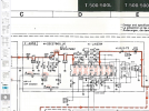
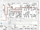
Most of that resizes too small for me to read. Can you post the PDF ? I can't grab one from other sites from this computer.

What I can make out though it looks like the F4854 board contains the MPX decoder. Not a whole lot here, MPX on a chip pretty much. Input from the detector should be through dC39, magic happens in the IC, output through dQ6 L and R. Q7 looks like it would short output to ground for muting.

The question is how exactly it switches from mono to stereo. If it pulls the mono upstream of the IC, like through that split in the connection between what I presume is the output of the detector and the input to the stereo decoder, then its bypassing that whole chunk and the problem could be anywhere between the input cap and output connections.

Other setups run signal through the MPX at all times, and the mono function just internally switches the IC or whatever so it doesn't decode, but the same parts are in the signal path.

The datasheet tells me that pin 9 is the mono pin and it can be run to a switch to force mono, or it can be tied to the IF strip to automatically switch to mono on weak signals.

a scope or even an old school signal tracer would make this a whole lot easier to debug. Honestly short of some voltage checks I'm not entirely sure I can make a lot of suggestions here to figure out the problem more precisely.
 
You can get the service manual with FM adjustments at hifiengine
This is an easy to align tuner - it may just need some adjustment. If your meter can measure AC and DC, you may be able to do many adjustments using "off the air" stations.
but first start with these 2 -
With a DC voltmeter, you can make sure the detector is zero'ed - done with antenna disconnected and on a blank station - Section 1, step 2-1
If not zero'ed, most won't do stereo.
Also you can do Section 2 FM stereo Adjustment step 1 - adjust dVR1 till stereo lights. Leave pot at center from where it lights from each rotation direction of pot.

These are 2 easy ones to start, don't touch anything else.
You can also compare pin levels tuner to tuner if a part is really bad.
After that, you can look at the DC level out on pin 13 of the IF chip LA1231 to peak the RF front end, etc. - But see if this the above works first.
 
Most of that resizes too small for me to read. Can you post the PDF ? I can't grab one from other sites from this computer.

What I can make out though it looks like the F4854 board contains the MPX decoder. Not a whole lot here, MPX on a chip pretty much. Input from the detector should be through dC39, magic happens in the IC, output through dQ6 L and R. Q7 looks like it would short output to ground for muting.

The question is how exactly it switches from mono to stereo. If it pulls the mono upstream of the IC, like through that split in the connection between what I presume is the output of the detector and the input to the stereo decoder, then its bypassing that whole chunk and the problem could be anywhere between the input cap and output connections.

Other setups run signal through the MPX at all times, and the mono function just internally switches the IC or whatever so it doesn't decode, but the same parts are in the signal path.

The datasheet tells me that pin 9 is the mono pin and it can be run to a switch to force mono, or it can be tied to the IF strip to automatically switch to mono on weak signals.

a scope or even an old school signal tracer would make this a whole lot easier to debug. Honestly short of some voltage checks I'm not entirely sure I can make a lot of suggestions here to figure out the problem more precisely.
Thanks for getting back. I am a retired person learning electronics at a late stage. I was wondering if I could pinpoint the defect by probing both tuners at the same connections and determine “from where” or “upto where” is the bad tuner good or bad. Wonder if that can be done?
 
You can get the service manual with FM adjustments at hifiengine
This is an easy to align tuner - it may just need some adjustment. If your meter can measure AC and DC, you may be able to do many adjustments using "off the air" stations.
but first start with these 2 -
With a DC voltmeter, you can make sure the detector is zero'ed - done with antenna disconnected and on a blank station - Section 1, step 2-1
If not zero'ed, most won't do stereo.
Also you can do Section 2 FM stereo Adjustment step 1 - adjust dVR1 till stereo lights. Leave pot at center from where it lights from each rotation direction of pot.

These are 2 easy ones to start, don't touch anything else.
You can also compare pin levels tuner to tuner if a part is really bad.
After that, you can look at the DC level out on pin 13 of the IF chip LA1231 to peak the RF front end, etc. - But see if this the above works first.
I have downloaded the manual of a similar tuner from HiFiEngine. The manual for this particular tuner is not available anywhere, and that’s why the similar manual.

I suspect that the IFT coil in the front end is damaged. It is impossible to find a replacement. I plan to make one myself.

I also suspect both the coils T2 and T3 to have got damaged. That’s the reason I thought of using the good tuner to find out from where in the signal path it may be good.

Thank you for your suggestion which I shall check tomorrow.
 
If you suspect RF or IF problems, you can get or make an RF detector to rectify the signal and make a DC level that can be measured. The best ones have an ADlog amp on board and require DC power, they used to sell them on EBay. But you can make a passive version with a germanium diode, cap, and resistors.
The probe DC level is directly proportional to the RF/IF level. Then compare the two tuners to see where along the signal path the signal changes amplitude from the good one.
 
Thanks for getting back. I am a retired person learning electronics at a late stage. I was wondering if I could pinpoint the defect by probing both tuners at the same connections and determine “from where” or “upto where” is the bad tuner good or bad. Wonder if that can be done?
I don`t see why not, just make sure both tuners are setup/tuned the same way, receiving the same strength signals from the antenna, or individual connected T antennas comparing various circuit readings from the good tuner to the bad tuner, as their circuits layout is identical.
I trouble shot and fixed quite a few stereo amps/receiver audio sections back in my early days with no service manuals that had one channel perfectly functioning by comparing the voltages between the good side and non functioning side (I called the good channel my "living schematic")
I made sure the power supply seemed to be reasonably functional first.
 
I don`t see why not, just make sure both tuners are setup/tuned the same way, receiving the same strength signals from the antenna, or individual connected T antennas comparing various circuit readings from the good tuner to the bad tuner, as their circuits layout is identical.
I trouble shot and fixed quite a few stereo amps/receiver audio sections back in my early days with no service manuals that had one channel perfectly functioning by comparing the voltages between the good side and non functioning side (I called the good channel my "living schematic")
I made sure the power supply seemed to be reasonably functional first.
Please forgive my ignorance, as I am still learning things. Do I connect the ground of both tuners together or should I leave them independent?
 
Please forgive my ignorance, as I am still learning things. Do I connect the ground of both tuners together or should I leave them independent?
I don`t see why you would need to do that, just measure one tuner section with your meter and then transfer your meter`s leads meter negative lead connected to the tuners frame to the other tuner and measure the same circuit section/component for reading comparing any significant difference between the 2 tuners.
 
Here's the link to a "RF to DC probe" I mentioned above. This is dirt cheap for what it does. The AD8307 performs a function similar to the circuit in a tuner that determines the signal strength and sends the level to a meter. But it's much more linear and accurate. The "log amp" converts the RF input amplitude to a log output, DC.
Look up at the data sheet for the AD8307 for a better understanding. You need to stick the assembled board into an old pen or marker body and solder on tip, etc. to finish.
RF Probe AD8307 based
 
You can get the service manual with FM adjustments at hifiengine
This is an easy to align tuner - it may just need some adjustment. If your meter can measure AC and DC, you may be able to do many adjustments using "off the air" stations.
but first start with these 2 -
With a DC voltmeter, you can make sure the detector is zero'ed - done with antenna disconnected and on a blank station - Section 1, step 2-1
If not zero'ed, most won't do stereo.
Also you can do Section 2 FM stereo Adjustment step 1 - adjust dVR1 till stereo lights. Leave pot at center from where it lights from each rotation direction of pot.

These are 2 easy ones to start, don't touch anything else.
You can also compare pin levels tuner to tuner if a part is really bad.
After that, you can look at the DC level out on pin 13 of the IF chip LA1231 to peak the RF front end, etc. - But see if this the above works first.
The detector couldn’t be zeroed by moving the slug from right in to right out on the T2. Pin 7 showing 9 volts, however pin 10 is at a satisfying 5.7 volts. That’s the reason I mentioned that I suspect the detector coil may be damaged.

The DC level on pin 13 of LA1231 was 2+ volts with a strong channel tuned into. But by tweaking the IF coil, and two trimmers on the gang, I could increase it to almost 3 volts.
 
<font style="vertical-align: inherit;"><font style="vertical-align: inherit;">Repair the 10M frequency deviation fault of the Shanshui T-500 radio head</font></font>
(出处: 矿石收音机论坛)

Hello all, I happened to stumble across this post (link posted above) on another site. He has in post #4 second paragraph described the exact problem that I too have. He has also recommended the solution for it.

Let me now check if by adding a capacitor externally I am able to get any better results.
 
<font style="vertical-align: inherit;"><font style="vertical-align: inherit;">Repair the 10M frequency deviation fault of the Shanshui T-500 radio head</font></font>
(出处: 矿石收音机论坛)

Hello all, I happened to stumble across this post (link posted above) on another site. He has in post #4 second paragraph described the exact problem that I too have. He has also recommended the solution for it.

Let me now check if by adding a capacitor externally I am able to get any better results.
So, I tried connecting ceramic capacitors of small values to the quadrature detector coil (across pin 9 and 10 of the IC) and was able to lower the voltage at pin 7 of IC LA1231N (from 9 volts to 5.5 volts) to almost 0 volt across pin 7 and pin 10. I noticed two things, firstly the volume of audio on my headphones (which I had connected to the “out” of the tuner) had become very silent, and secondly the slug movement of the discriminator coil did not change any reading of V at pin 7.
 
Hello everyone and good evening.
I would like to conclude my post today.
i have finally been able to trace the problem. The capacitor on the discriminator can (T2) was faulty. I did suspect it to be so because of the high voltage at pin no 7 on LA1231N. So I connected a trimmer capacitor across the coil of the discriminator can. And suddenly at a sweet spot while turning the trimmer cap, I not only got stereo, but also the volume of the signal increased significantly.
Hope people searching for remedies for a similar problem find this thread and their fm comes back to life.
 
Back
Top Bottom