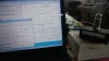
I've been building again. I had just re-built and calibrated my B&K 707 Dyna Jet tester, which I've been very happy with. I had been looking around, though, for a reasonably priced instrument to do more in-depth tube analysis and matching and found Ronald Decker's uTracer and decided to give it a try (google uTracer and you'll find his excellent website). Well, I bought the full kit and it was delivered quickly from the uTracer HQ in Holland through the support of Ronald and his wife Marie-Jose. I haven't seen much about it on AK, so I thought I'd share a few photos and notes about my initial experience with it and see if others have tried it.
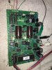
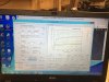
The build took a few hours of careful work (a dense board with small parts--only a couple SMD parts, pre-installed--thanks Ronald!) and all worked well right off the bat, including the RS232 interface (via USB adapter) and an outstanding graphical user interface on my budget Windows 8.1 lap top. The construction manual is outstanding and basically has you build and test the unit a section at a time. Reminded me fondly of my Heathkit building days!
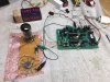
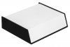
I bread boarded a 9 pin noval and 8 pin octal socket for some initial testing, but have a case and parts on order for a permanent housing (see the website for fully realized examples). The board and the parts are all high-quality and, to me, the circuit is remarkable for its ingenuity and effectiveness, consisting of a series of pulsed power supplies controlled by an on-board PIC and the PC GUI. You have to provide your own tube socket/switching scheme and builders have done some clever set ups (on the website under "testimonials").
The latest version 3 will generate anode and screen voltages up to 400 VDC. The whole thing runs on a surplus 18V 1.7A PC power supply I had on hand. Filament supply (pulsed) is provided up to the power supply voltage limit and about 1.5A. An outboard supply would be needed for higher-current, low-voltage tubes or voltages above the power supply max voltage.
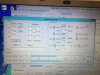
I tested a few tube types, including a bunch of dual 12A(X,T,U,V)7 types, some 7591's, a couple of 5881's and a whole lot of 6V6GT's on hand from a tube cache I recently acquired. After a bit of study and practice, the instrument is pretty intuitive and straight forward to use and produces all sorts of excellent output curve traces for just any tube type you can hook up to it. Also very handy is a 'quick test' feature that tests the tube against the bogey values you put in from the tube data sheet and generates a printed quality report with mutual conductance, plate resistance, amplification factor, and plate/screen current at a given bias set point against tube sheet values, expressed as a number and % of the bogey values. Another neat feature is the ability to test both sides of dual triodes at the same time.
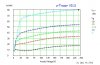
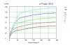
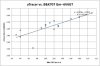
I'll show some examples of the output in the next couple of posts. I also decided to compare the uTracer mutual conductance values against the ones from my B&K 707 and I'll show that, too (short answer is they compared very well). The curves and quick test report below are for a (sadly) weak 5881 power pentode.
Interested in any questions and observations, particularly experiences from anyone with uTracer experience.
Dave
The build took a few hours of careful work (a dense board with small parts--only a couple SMD parts, pre-installed--thanks Ronald!) and all worked well right off the bat, including the RS232 interface (via USB adapter) and an outstanding graphical user interface on my budget Windows 8.1 lap top. The construction manual is outstanding and basically has you build and test the unit a section at a time. Reminded me fondly of my Heathkit building days!
I bread boarded a 9 pin noval and 8 pin octal socket for some initial testing, but have a case and parts on order for a permanent housing (see the website for fully realized examples). The board and the parts are all high-quality and, to me, the circuit is remarkable for its ingenuity and effectiveness, consisting of a series of pulsed power supplies controlled by an on-board PIC and the PC GUI. You have to provide your own tube socket/switching scheme and builders have done some clever set ups (on the website under "testimonials").
The latest version 3 will generate anode and screen voltages up to 400 VDC. The whole thing runs on a surplus 18V 1.7A PC power supply I had on hand. Filament supply (pulsed) is provided up to the power supply voltage limit and about 1.5A. An outboard supply would be needed for higher-current, low-voltage tubes or voltages above the power supply max voltage.
I tested a few tube types, including a bunch of dual 12A(X,T,U,V)7 types, some 7591's, a couple of 5881's and a whole lot of 6V6GT's on hand from a tube cache I recently acquired. After a bit of study and practice, the instrument is pretty intuitive and straight forward to use and produces all sorts of excellent output curve traces for just any tube type you can hook up to it. Also very handy is a 'quick test' feature that tests the tube against the bogey values you put in from the tube data sheet and generates a printed quality report with mutual conductance, plate resistance, amplification factor, and plate/screen current at a given bias set point against tube sheet values, expressed as a number and % of the bogey values. Another neat feature is the ability to test both sides of dual triodes at the same time.
I'll show some examples of the output in the next couple of posts. I also decided to compare the uTracer mutual conductance values against the ones from my B&K 707 and I'll show that, too (short answer is they compared very well). The curves and quick test report below are for a (sadly) weak 5881 power pentode.
Interested in any questions and observations, particularly experiences from anyone with uTracer experience.
Dave