UPDATE: INTERNAL HEATER VOLTAGE CORRECTION FOR HIGHER-CURRENT 6.3V TUBES
After using the uTracer a good bit I discovered a phenomenon that turns out to have been well-discussed by the uTracer user community and is dealt with in Ronald Decker's FAQ. When measuring 6.3 V filament tubes with relatively high current draw (0.8-0.9A, say a 7591A or 6L6), I noticed that test results for Gm, Ia, Is etc were about 10% lower using the internal supply set to 6.3V compared to my bench DC supply set a 6.3VDC.
I had also seen this effect before when I put extra RFI suppression in the Anode, Screen, Grid, and Cathode leads (in addition to the ones already installed on the circuit board). A little is good, so more should be better, right? Not so much, it turns out. When I removed these extra multi-wind beads, the results returned to those I had seen during breadboard testing without the extra beads. I figured this was from excess impedance in the circuit from the added suppressors with the pulsed voltages from the uTracer.
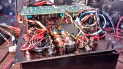
I had installed, as recommended by Ronald in the Construction Manual, the multi-turn RFI beads in the filament leads and I believe the added reactance (impedance) is holding down the delivered average filament voltage to the tube. After reading some online dialogue from the user community and then Ronald's FAQ on the heater supply, I confirmed that this is likely the case. Ronald has held forth on his website FAQ on how this can occur with low voltage/high current tubes, but I believe it was happening on mine for 6.3V tubes for the reasons given below.
The RFI suppressors I used (Mouser 807-4212R-4 API-Delevan--one in each leg) with all the turns used have something like 300-400 ohms impedance at the 19.5 kHz pulse frequency. This combined with that of the ferrite beads in the socket wiring, plus stray inductance of the wiring itself was probably contributing to the slump in filament voltage. Ronald explains that the pulsed filament voltage is a product of a the duty cycle used by the filament supply based on the voltage entered on the GUI and the power supply max voltage. My 18V supply, being lowest in the recommended range, probably contributed as well.
I ran some tests and figured for the 7591 and 6L6 that running the voltage setting for the internal supply at about 7.0V more or less equalized the results compared to 6.3VDC from my bench supply. Some folks, it turns out, calculated correction curves for any given tube and entered the corrected filament voltage in their saved set up file for the tube. Ronald cautions on using an overall correction factor, as the inductance can vary due to multiple factors, eg. depending on the tube socket you're using, etc.
The simplest solution is to use an outboard DC power supply, as Ronald recommends and that's what I'm doing, but I thought I'd pass this along for those of you who have built and weren't aware. By the way, I compared the results for 12V tubes like the 12AX7 and the difference between results using the internal supply vs. the external DC supply were negligible on my unit. I'm considering removing the ferrite suppressors in the filament leads and seeing if that fully resolves the issue at some point.
Dave