• The move to the new server is done. There are some software and database maintenance updates in process. This has us passing the hat around to help out. We appreciate any donations. Seriously, even a dollar helps. The payment page may be found here - https://www.audiokarma.org/support.html

Vandersteen 2CI Burned Resistors

turnitup

No, the stereo won’t break the crystal...Oh CRAP!
I acquired a pair of Vandersteen 2Ci’s about 15 years ago, with known issues. I was about to get rid of them, but decided to dig into them to see if I could get them working again. One speaker had a blown tweeter, and a blown woofer. I tore the drivers down and was able to repair both of them. Both had spider connections that had been burned through. Buttoned speaker #1 up, and tested it, worked beautifully!

Speaker #2 also had a blown tweeter, also with a burned through spider connection. All other drivers were in working order. Tested #2, and everything worked but the mid. Tested the mid and it was good. Came to the realization that the issue was with the dreaded/complex Vandersteen crossover!

In further inspection, I think I have some burned resisters, but could use some help ID’ing my parts. Pictures to follow!
 
Last edited:
Register to hide this ad
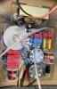
OK, here’s a picture of the “good” 2CI crossover:

E93EFD65-9CEF-4AED-AFD7-5351AEC6B2EC.jpeg

Just to the left of the top pot are the 3 burned parts. They are fine on this crossover, not on my other (this picture is for just for reference from the working speaker).

Here’s a zoomed in picture of the good #1, and bad #2 crossover (burned parts are obvious).

#1 Good crossover resisters:

F352404A-22E7-4386-A5D8-2644A8886DE2.png

#2 Damaged crossover (same parts as above):

9A577A07-C7AB-4DCF-BD35-E89E2570214B.png

The 3 seem to be connected in parallel. I think there are 2 - 12 ohm 5% resisters, but not sure what the 3rd part (the grey part on top) is…. Anyone???

Thanks for chiming in to help!
 
Last edited:
There are also two other resisters, that look like they have taken some excessive heat, I might replace these as well while I’m in there. What size are these? 68 ohm??? (Blue, grey, gold, gold). I’m a little thrown by the 2 gold bands on these. 5%, I get, but what about the other middle gold band?

Thanks in advance for the help.

37C48578-7706-4CD7-97C9-E3270E961002.png
 
The gray resistor should be a 20 ohm, according to the label.

Those look like 2 watt resistors. Though, with modern technology, you can probably fit new 3 watt resistors in place of those...

Regards,
Gordon.
 
Gold is a 0.1 multiplier. Therefore, that resistor would be 68 x 0.1 = 6.8 ohms.

Regards,
Gordon.
 
The gray resistor should be a 20 ohm, according to the label.

Those look like 2 watt resistors. Though, with modern technology, you can probably fit new 3 watt resistors in place of those...

Regards,
Gordon.

Thanks for the help on this Gordon, so I could replace the 2 - 2 watt resisters, and the 20 ohm resister (currently in parallel) with a single 3 watt resister? What about the 2 - 6.8 ohm resisters in parallel? Any single value resister to replace both of these with?
 
Do the multiple resisters in parallel, help with heat dissipation, versus a single higher value resister?
 
Thanks for the help on this Gordon, so I could replace the 2 - 2watt resisters, and the 20 ohm resister (currently in parallel) with a single 3 watt resister? What about the 2 - 6.8 ohm resisters in parallel? Any single value resister to replace both of these with?

No, I would use 3 watt resistors to individually replace all three. Use two 12 ohm, and one 20 ohm for the one set, and go back with two 6.8 ohm resistors for the other.

A single resistor that's capable of handling enough power, would be too long to fit in the space...

Regards,
Gordon.
 
Yes 3 help with power dissipation, you might even leave .25 to .5" between them for air flow.
They were obviously getting very hot.
I've heard people say that when they call asking about 3 burnt resistors, RV says to try
10 ohms for them.
I reverse engineered a pair here, and found 3 ten ohm, perhaps it is a minor revision for one or the other:
https://www.audiokarma.org/forums/i...erview-and-xo-schematic.913010/#post-13752530

Obviously put in what you found there, to keep them original, but I agree 3W or more each is better.
I think that they were deliberately undersized so that RV would know when people were driving them too hard.
 
Funny story, I had a guy on the West coast call me and say I had a (crazy) party and
we just kept turning it up. We blew every driver in my 2Ci's, he says please take them,
he sent them to me no charge, with all the drivers removed. Someday I'll dig into them.

I told him it was probably not worth the shipping cost but he said no problem.
 
Last edited:
No, I would use 3 watt resistors to individually replace all three. Use two 12 ohm, and one 20 ohm for the one set, and go back with two 6.8 ohm resistors for the other.

A single resistor that's capable of handling enough power, would be too long to fit in the space...

Regards,
Gordon.

Just to round out my education on this…am I always able to use higher wattage resisters with no impact, as long as I use the same ohm rating, and tolerance (analogous to being able to use higher voltage rated crossover capacitors, with the same capacitance rating, with no performance impact)?

Thanks for the education!
 
JA in the Stereophile review said that the 2Ci sounded best with the mid control at -1 or -2 dB.
Which might be the reason for slightly increasing those resistors.
 
Funny story, I had a guy on the West coast call me and say I had a (crazy) party and
we just kept turning it up. We blew every driver in my 2Ci's, he says please take them,
he sent them to me no charge, with all the drivers removed. Someday I'll dig into them.

I told him it was probably not worth the shipping cost but he said no problem.

Thanks for chiming in Pete, I’ve seen the reverse engineering work that you did on the 2Ci’s, very impressive and helpful.

I was surprised at how easy the drivers were to repair. At least with mine, they simply burned through at the spider connections. I unwound one loop off of the coil, and re-soldered. I was expecting total coil fry - I was exceedingly lucky. Maybe you’ll find the same when you tear into your donors! So much overhead on working on these though. Crossovers stapled and glued. Socks stapled and glued on the top and at the speaker connections. Richard definitely did not make these with the intent to be user repairable, without extreme pain and agony.

This is why they have literally been sitting around my place (in disrepair) for 15+ years! I’m now intent on getting these going again though. I think RV must own stock in a staple company…
 
Last edited:
That's all good to know, but he sent them without any drivers - oh well.
Yes, they are really overly complex, that's for sure.
 
Just to round out my education on this…am I always able to use higher wattage resisters with no impact, as long as I use the same ohm rating, and tolerance (analogous to being able to use higher voltage rated crossover capacitors, with the same capacitance rating, with no performance impact)?

Thanks for the education!

Correct. As long as the resistance value is maintained, and the power handling is equal or higher than original, it will be fine.

Regards,
Gordon.
 
Correct. As long as the resistance value is maintained, and the power handling is equal or higher than original, it will be fine.

Regards,
Gordon.

Thanks Gordon, what type of resister should I be ordering to replace these? Are these just carbon composite resisters? I tried Parts Express with no luck, but Mouser is overwhelming unless you use the absolutely correct vernacular in your search…just want to get this right!
 
Good luck getting those crossovers out.

Yeah, I’m very familiar with these beasts. I plan to cut these out and re-solder the resisters without removing the crossovers. May not be beautiful when I’m done, but it won’t be visible, and I’ll assure it to be a solid repair. Glued, stapled, and virtually encased in a thick clear coating. Nope, not removing, not going there - you win Richard Vandersteen…
 
I agree that you should cut the leads close to the old resistors, then clean the old
lead, and twist them to the new ones. When you solder them, hold the old lead tight down
close to the board with long nose pliers so that the heat doesn't desolder the end down on the
circuit board. You can probably get away with not doing this but just hold the iron
there long enough to properly flow the solder.
 
Back
Top Bottom