• The move to the new server is done. There are some software and database maintenance updates in process. This has us passing the hat around to help out. We appreciate any donations. Seriously, even a dollar helps. The payment page may be found here - https://www.audiokarma.org/support.html

Variac powered, fused, dim bulbed, and metered, switched bench power?

klamsoss

Be willing to fail and try again.
Good morning race fans!
Relative newbie looking for some input on a DIY bench power monitoring station...
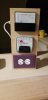
I have been working on tube gear for a year or so and the variac is a great tool. I have a 15A staco unit that weighs enough to use it for home defense. I also put together a DIY AC meter stack. See pic 1. I plug my meter stack into the variac and that allows me to monitor both VAC and current (up to 3A) as I bring voltage up with the variac.

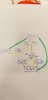
Now I'm doing some solid state amp restorations and I understand that a dim bulb tester is a MUST. I also understand that for performance testing higher power solid state gear, I may need more than 3A. My bench space is limited (isn't it always?) so, my plan is to do more with less real-estate by adding a switch to the stack, and a similarly metered 10A side with a dim bulb tester built right in line. See pic 2 for schematic: black is hot, yellow is neutral, green is ground. Fuses are marked with an X.
This would give me a 3A side, and a 10A side each with accurate-to-their-range meters, fuses before the meters, and the ability to switch back and forth between them, all while monitoring incoming AC voltage. Plus, I have the master switch to shut off the power to the 10A side if my bulb doesn't dim.

Before I cut apart my current "ack stack" (get it...? "AC" pronounced "ack"......... *crickets*) to add the 10A side, I wanted to ask the AudioKarma braintrust if they see any issues with the schematic or have recommendations.
Does the schematic make sense?
Does the ground need to be wired to the switch (I suspect not)?
Would it be wise to add a 2nd switch allowing me to use the 10A side without the bulb?
Any other ideas?

Many thanks to any and all who chime in!
 

Attachments

  • 20200202_220749.jpg
    20200202_220749.jpg
    25.8 KB · Views: 128
  • 20200302_102353.jpg
    20200302_102353.jpg
    41.2 KB · Views: 127
Register to hide this ad
G'day.
IMO the DBT just offers limiting both voltage and current. Many variac users setups don't use one. And the dbt is just another tool. I.e. if you come across a FET amp. sensitive to a variac limiting voltage. Basically just a quickie test to reveal a short and check if your repairs worked.
I don't see why you have to tear down the current setup just assemble a dbt. rare to see a home stereo amp with a ground lug but i.e. ss guitar amps come with them so adding a ground is not biggie.
 
Just to add.. nothing wrong w/your setup as it's fused.. but wouldn't one of those mini circuit breakers be better than buying fuses?
Another thing a dbt can be portable if bench space is limited or testing out of shop.
 
The mini circuit breaker is actually a brilliant idea... Actually, my variac blows the breaker if I forget to turn it down to 40-50V before turning it on.:idea: This gives me the idea of building a mini breaker just for my test bench, so I don't have to go down 2 flights of stairs to the main breaker panel whenever I short something or forget to turn the variac down.
Would single pole 240VAC breakers work even though I'm using 120VAC? I don't see why they wouldn't...

Anyway, the idea with putting all this in one unit is to save space, but also to be able to monitor various aspects of performance while evaluating a DUT. I already know from my tube work that monitoring the AC line voltage is a necessity, since my wall voltage can drift by +/-2 volts over the course of an hour, and can range from 114 up to 126 VAC. I also know that current monitoring is important for testing tube equipment even beyond startup. But I haven't yet learned if current monitoring is as important for solid state equipment (like I said, I'm not totally green, but I ain't grey, either, so I'm still learning a lot very quickly). It sounds like maybe current monitoring is not as important for solid state gear, as long as I am using a DBT at startup (i.e. I can use one or the other because they accomplish the same thing, but the dim bulb seems to be the safer option).

Am I wrong on that? I'm not very deep into solid state work yet, so I really don't know.:dunno: If I'm unlikely to ever need to specifically monitor AC line current while testing solid state gear, then omitting the 10A meter in my proposed setup would save me some trouble and I could fit the bulb fixture and switches onto my existing rig. But it's not that hard to rig up a new panel, either, so if it IS likely that I'll want to monitor AC line current over 3 amps, I'll just build it in now.

I also thought the variac was generally a no-no for solid state as there can be components which may not function at all until you hit 80-85 VAC and then all the sudden, they activate and things go poof pretty quickly. So my thought was that in practice, for solid state gear I'd normally either plug the whole thing directly into the wall, or just set the variac at whatever line voltage the device manufacturer specifies for testing and setting bias/balance/offset/etc. whilst using the DBT as the primary safety net.

Many thanks!
 
confession time. I don't own a dim bulb tester. Never really felt the need for one.

I have a variac that runs through a volt and an ammeter. 2 amp ammeter with a 2 amp fuse to protect it. I think the variac is good for 7 amps. If something is going well and truly wrong, you'll see the ammeter wind up quick enough to shut things down before they blow up. If you don't catch it, the relatively low amp fuse will save it.

grounds go to the switch just in case something shorts to the case of the switch. Same reason metal junction boxes get grounded.
 
While I have a dim bulb tester I don't use it much anymore. I guess I would if I hadn't got a variac with a voltage meter and a small amp/watt meter I bought off Ebay.
 
testing and setting bias/balance/offset/etc. whilst using the DBT as the primary safety net.
You won't get a line voltage nor be able to set bias etc.. using a dbt. Again the dbt is most useful for a pre check for shorts and after a repair is made. Basically a budget minded tool I oft recommend for newbies. But also handy if you travel to test a stereo.
 
IMHO a DBT tester is a MUST... especially if you live in an area of country frequented by lightning storms.
When I had my TV shop I used it anytime I replaced a fuse!
The DBT should be bypassed once operation is established and before alignment...

My bench supply is as follows:
LINE > True isolation transformer > variac > DBT
this is used in the evaluation phase for major problems, shorts, etc....

then switch to:
LINE > True isolation transformer
for tuning, bias, noise trouble shooting, etc

final test straight to LINE
 
Sounds like there's little need to have 10A current monitoring. Maybe I'll skip that and just put in a DBT on the existing box, with a SPDT bypass switch that controls if it is DBT or 3 amp AC current meter.
 
Last edited:
Incandescent bulbs are plentiful in my area. Lots of the rural folk hate them new fangled LED and florescent types. Probably has something to do with some perceived government plot to control our minds. :rolleyes::biggrin:
 
Do the same as some others, isolation transformer, to variac (w/volt & amp) then a dim bulb tester....if that amp gauge starts rising, turn it off.

Always better to have more amps than needed on the variac, and/or, on the bucking transformer, 2 MkIIIs, tube preamp and tube tuner takes a bit of power when warming up (-;

Always check the watts ratings of the equipment and select bulb wattage accordingly.

Regards,
Andy
 
Okay, what about this schematic?
Pen line is black/hot.
Yellow is white/neutral.
Green is ground.

My thought here is that I'll have just added a DBT onto the existing AC stack. But I'm not sure if I can use a buss setup for the neutral lead. Would those neutrals coming off the outlets need to have diodes on them to prevent reverse current flow?
 

Attachments

  • 20200307_215328.jpg
    20200307_215328.jpg
    29.5 KB · Views: 26
Okay, what about this schematic?
Pen line is black/hot.
Yellow is white/neutral.
Green is ground.

My thought here is that I'll have just added a DBT onto the existing AC stack. But I'm not sure if I can use a buss setup for the neutral lead. Would those neutrals coming off the outlets need to have diodes on them to prevent reverse current flow?

NO diodes on the Neutral, it is an AC current conductor. Buss configuration is fine as long as you keep your measuring and switching only on the 'hot' side, and are aware that heavy currents cause voltage drops along the neutral wire just like they do the hot wire.
Neutral conductors should not be broken by anything, they are the 'current return path' for the hot side. Unless you need isolation, then the hot and neutral are both connected to the isolation transformer input. Once you have an isolation transformer in the circuit you have complete electrical separation, so the transformer output side has, by definition of 'isolation', no 'hot' and 'neutral' conductors. Neutral is a 'Wiring Code' concept, and is 'bonded' to 'earth' or 'safety' ground, usually at the incoming distribution panel. It is also bonded to ground at most of the outdoor power line poles that have a 'neutral' conductor. The power supply transformer in your amp provides that same isolation as well as providing different output voltage and current windings. Power distribution is actually a more complex subject than most user realize.
If you are going to use a DBT and a Variac at the same time you need a good understanding of how they work and what their jobs are. A DBT provides a ballast that limits power flowing into its load. A Variac is a variable transformer, when you step down the voltage you step up the available current by the same ratio, it is not intended to be a ballast or power limiter.
 
I think the idea isn't bad, but overkill.
My bench is also small, so my DBT is stored in a drawer, I only find a need to get it out maybe 5 times a year.
I also have a variac - same thing - I rarely use it (I only work on SS).
Ya, make sure you understand the use for each of those devices.
I'm not much help, but I believe you are overthinking this.
 
Ahhh... duh. I'd have rapidly remembered (before construction) that diodes on ac lines do a different thing than on DC lines, but thanks for the sanity check. I've only put together diode rectifiers like... too many times. I don't know what I was thinking...

Anyway, my new approach is to have a separate outlet that is 10A metered, always on. The 3A network will be switchable between DBT OR 3A metered. The assumption would be that if DBT is being used, I would have the variac set at whatever test voltage is required by the manufacturer of the equipment I'm working on.

New schematic pictured. The switch is a 3 position (on-off-on) dual pole switch, so I can completely turn the 3A side of things off, or choose between DBT or meter.

I understand neutral is the current return path. What I'm wondering now is if there is a problem with having either the dbt or the meter effectively after the 3A outlet, with an open circuit after that. My intuition says no problems with that setup. But I've been wrong a lot in my life.
 

Attachments

  • 20200311_124839.jpg
    20200311_124839.jpg
    18.8 KB · Views: 12
The DBT can go before or after the 3A fuse or breaker, no matter electrically, but personally I would put the fuse/breaker first before everything.. The current meter should be the last thing in the chain right before the load (Amp input). If you are going to use the variac and the DBT at the same time put the DBT after the variac. If you have all three connected there are 4 possible places to monitor AC voltage: the whole circuit input voltage, at the input to the variac, which is your mains voltage; after the variac but before the DBT, which is set to your units specified input AC voltage; after the DBT, which is the actual input voltage under load limited by the DBT. All of these can tell you different things about your amp you may need to know. Or it may just be a bunch of extra work wiring it up. Study and apply Kirchoff's Laws, they will greatly enhance your troubleshooting abilities. :blah::rolleyes: Maybe TMI.

EDIT: I don't have a variac. When using the DBT in the process is over I put a 5A breaker in place of the bulb.
 
Last edited:
Merlynski, any information given in good faith and good intention is welcome information. I'm learning.

Error in my schematic.
The DBT should have only hot going in, and hot coming out, so that the bulb is actually in line. Essentially the same as the 3A meter setup, with DBT in place of the meter.

With a single power cord feeding the "stack", I have the flexibility to plug directly into the wall for DBT and 10A outlet use, or plug the whole thing into the variac if I need to do tests more sensitive to specific input voltages.
I should verify that there's no meaningful voltage drop across the switch and meters.
 
Merlynski, any information given in good faith and good intention is welcome information. I'm learning.

Error in my schematic.
The DBT should have only hot going in, and hot coming out, so that the bulb is actually in line. Essentially the same as the 3A meter setup, with DBT in place of the meter.

With a single power cord feeding the "stack", I have the flexibility to plug directly into the wall for DBT and 10A outlet use, or plug the whole thing into the variac if I need to do tests more sensitive to specific input voltages.
I should verify that there's no meaningful voltage drop across the switch and meters.

The switches should not have any meaningful voltage drop, current meters do (because of the way they work) have a small voltage drop, usually, by design, and not significant if chosen carefully. My OCD/perfectionism tells me that if you really want the MOST accurate information the input voltage to the amp should be measured after the current meter.
Enjoy your project, but be careful, they are habit forming |:rflmao:|.
 
Back
Top Bottom