• The move to the new server is done. There are some software and database maintenance updates in process. This has us passing the hat around to help out. We appreciate any donations. Seriously, even a dollar helps. The payment page may be found here - https://www.audiokarma.org/support.html

Varistor VDT 1212 Yamaha C4

Hifibythekg

Super Member
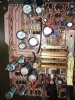
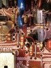
Just want to check whether this photo shows a VD 1212 varistor, next to its printed symbol on the pcb, facing the WRONG way?

It’s currently residing in a Yamaha C4 preamp on the Function Board.

Also, what’s the best way to test these components out of circuit.. a DMM or a cheap transistor tester?

Would appreciate any advice.
35C0AE87-13C6-450D-92D5-91926ABD5CB3.jpeg
 
Register to hide this ad
Thanks Dave.
These highlighted VD1212’s aren’t in the SM and have no silk screen markings on the board.
Are you able to tell if they’re both facing in the correct direction?
The one at the top of the frame has black end nearest to the top of the photo, bottom varistor has black nearest to the bottom of the photo.
(Hum in my C4 isn’t yet resolved so checking on every possibility.)
0A4C186C-0E8D-4D7D-BE8C-0C57C9801DBB.jpeg
 
Thanks Dave.
These highlighted VD1212’s aren’t in the SM and have no silk screen markings on the board.
Are you able to tell if they’re both facing in the correct direction?
The one at the top of the frame has black end nearest to the top of the photo, bottom varistor has black nearest to the bottom of the photo.
(Hum in my C4 isn’t yet resolved so checking on every possibility.)
View attachment 2474139
If they are "working", then they are in the correct orientation. Otherwise smoke signals would have been sent up long ago. FYI, the Red end is the Kathode (or Cathode). The same as the black stripe on 1N4148 is the Kathode.
If you suspect them, replace them each with a pair of 1N4148 in series just like the silkscreen shows in the previous photo. Both black stripes pointing the same direction.
 
Thanks Dave.
These highlighted VD1212’s aren’t in the SM and have no silk screen markings on the board.
Are you able to tell if they’re both facing in the correct direction?
The one at the top of the frame has black end nearest to the top of the photo, bottom varistor has black nearest to the bottom of the photo.
(Hum in my C4 isn’t yet resolved so checking on every possibility.)
View attachment 2474139
Hum is more than likely a faulty ground, or bad electrolytic capacitor. Rarely is hum caused by a varistor diode unless one outright shorted. Look closely for any signs of bad solder joints. They can appear as a tiny "ring" around component leads, but sometimes are nearly impossible to spot. Touch up any and all "iffy" looking solder joints. And unscrew -> retighten any screws that are used for grounding.
**All work done UNplugged from the wall of course.
 
Thanks Dave.
These highlighted VD1212’s aren’t in the SM and have no silk screen markings on the board.
Are you able to tell if they’re both facing in the correct direction?
The one at the top of the frame has black end nearest to the top of the photo, bottom varistor has black nearest to the bottom of the photo.
(Hum in my C4 isn’t yet resolved so checking on every possibility.)
View attachment 2474139
In your photo, look to the left of the selector switch at the 4 "dark" resistors. The board also looks to be darkened. Areas like that where components get hot are prime candidates for having cracked solder joints. Plus those resistors could be out of tolerance from running so hot so check their values. You will have to pull one end of each since they appear to be in "series-parallel". Check for any other "hot spots" too for cracked solder joints, and/or out of spec components.
 
You will have to pull one end of each since they appear to be in "series-parallel".
They are in series-parallel -- Resistor divider network to drop the MC pre-amp rails down to +/- 5 v from the +/- 30 rails There are four sets of 4 ea. 820Ω 1/4 watt carbon film.
 
They are in series-parallel -- Resistor divider network to drop the MC pre-amp rails down to +/- 5 v from the +/- 30 rails There are four sets of 4 ea. 820Ω 1/4 watt carbon film.
Now that you mention it, I see 3 more pairs that look like they have gotten a bit "toasty warm", but not as bad as those first 4. Still candidates for checking them, and their solder joints.
 
They are in series-parallel -- Resistor divider network to drop the MC pre-amp rails down to +/- 5 v from the +/- 30 rails There are four sets of 4 ea. 820Ω 1/4 watt carbon film.
In the first post, just above "SW124" looks to be a pair of resistors that got a bit hot too. Worth checking as well.
 
n the first post, just above "SW124" looks to be a pair of resistors that got a bit hot too. Worth checking as well.
Check D121 and 122 6v zener diodes . Two pair of parallel 6.8KΩ 1/4 watt carbon film. R191/193 and R192/194.. Or a problem with TR175 / 176 dual JFET's.
 
Check D121 and 122 6v zener diodes . Two pair of parallel 6.8KΩ 1/4 watt carbon film. R191/193 and R192/194.. Or a problem with TR175 / 176 dual JFET's.
Sure thing. Voltages being "off" can contribute to a "hum". You're the "Master" at these Yamaha Brother. :thumbsup: Hope the JFETs aren't damaged. Resistors and Zeners are cheap and plentiful.
 
Huge thanks to you both for this attention and advice!
If I’m also getting a bit of crossover between Aux and Tuner.. any other places to check? Could a random diode or cap cause this also?
Have serviced one of the cartridge load switches, could the other one if gunked up be the cause of hum or crossover?
Currently checking for solder bridges and cold solder joins. Best running order for tasks?
1. Check zeners and resistors.
2.Clean second cartridge load switch.
3. Recap the entire amp.
Sound sensible?
Turning the Tape function switch has no effect at all on the hum and makes no audible sound at all, this is normal yes?
 
Huge thanks to you both for this attention and advice!
If I’m also getting a bit of crossover between Aux and Tuner.. any other places to check? Could a random diode or cap cause this also?
Have serviced one of the cartridge load switches, could the other one if gunked up be the cause of hum or crossover?
Currently checking for solder bridges and cold solder joins. Best running order for tasks?
1. Check zeners and resistors.
2.Clean second cartridge load switch.
3. Recap the entire amp.
Sound sensible?
Turning the Tape function switch has no effect at all on the hum and makes no audible sound at all, this is normal yes?
@avionic is way more familiar with this unit than I am. However a shotgun "full recap" isn't the way to go until the "problem(s)" can be rectified. Fix it first, then continue.
There is what is called a "crosstalk" specification. It defines how much "bleed over" is acceptable. That can be crosstalk between channels as well as crosstalk between sources. It has to do mainly with how close traces and/or wires are to each other where the signal can be "inducted" to the adjacent trace (or wire), and heard faintly in the background. Switches that are heavily tarnished can also cause it as the silver "spreads" out it can conduct. As far as this unit is concerned, someone else can tell you how much is "normal".
But by all means, cleaning switches is always a good step to resolving issues. Clean them, dry them, then test it out to see what "issues" remain. It checks them off the list of possible culprits.
 
Thanks Skywatcher, points noted and very helpful.

One additional symptom. When Phono 1 and 2 are selected the hum is only / mostly through the Left channel. When MC is selected the hum has equal volume through both channels. Any components or locations to especially check?

Resolving this imbalance may not cure the hum, but would be good to know what’s causing this.
 
Checked the two 2sk100 dual jfets...

I swapped them over...

Result: the opposite hum effect occurs!

That is, the hum now comes through mostly on the right channel.

Can the 2sk100’s be replaced?
 
Checked the two 2sk100 dual jfets...

I swapped them over...

Result: the opposite hum effect occurs!

That is, the hum now comes through mostly on the right channel.

Can the 2sk100’s be replaced?
If you can find them, or an equivalent substitute, yes. You can use matched pairs of single jfets and thermally couple them. Again, finding them is the problem.
 
Lots of commentary around this particular component on AK, but found it very hard to find specific solutions that people have confirmed have worked successfully..
 
Back
Top Bottom