• The move to the new server is done. There are some software and database maintenance updates in process. This has us passing the hat around to help out. We appreciate any donations. Seriously, even a dollar helps. The payment page may be found here - https://www.audiokarma.org/support.html

Vintage Newbie with Vintage SX-780 no relay click - seeking advice

CapitalSon

New Member
Hello All,

I acquired this sx-780, which had been abandoned in an office move in the 90's and put it in my garage as a retirement project, well that is here now. Yesterday I got it out, and powered up without speakers.
Lights on, LED's work( tape monitor, Stereo), Tuning meter works. I tested the fuses for continuity in pace and all were good. Nothing appears to be fried in the unit. I am waiting for some parts to test the phones output.

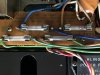
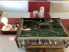
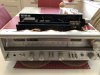
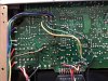
I have read in the forum that the relay should click after ~5 secs - I do not get any click with no speakers attached. I have attached pics of the unit.

Can I test the relay itself? How to tell if the relay is bad or it's not getting the right signals?

I am a novice at this, have a Beckman meter, waiting for a solder kit to arrive.

I don't want to damage the sx780, I love it so far and want to hear some classic rock from this classic receiver.

All advice welcome and thanks...
 

Attachments

  • IMG_0363.jpg
    IMG_0363.jpg
    100.4 KB · Views: 34
  • IMG_0364.jpg
    IMG_0364.jpg
    127.4 KB · Views: 33
  • IMG_0365.jpg
    IMG_0365.jpg
    154.8 KB · Views: 34
  • IMG_0366.jpg
    IMG_0366.jpg
    151.9 KB · Views: 33
  • IMG_0367.jpg
    IMG_0367.jpg
    105.8 KB · Views: 34
Register to hide this ad
Hello All,

I acquired this sx-780, which had been abandoned in an office move in the 90's and put it in my garage as a retirement project, well that is here now. Yesterday I got it out, and powered up without speakers.
Lights on, LED's work( tape monitor, Stereo), Tuning meter works. I tested the fuses for continuity in pace and all were good. Nothing appears to be fried in the unit. I am waiting for some parts to test the phones output.

I have read in the forum that the relay should click after ~5 secs - I do not get any click with no speakers attached. I have attached pics of the unit.

Can I test the relay itself? How to tell if the relay is bad or it's not getting the right signals?

I am a novice at this, have a Beckman meter, waiting for a solder kit to arrive.

I don't want to damage the sx780, I love it so far and want to hear some classic rock from this classic receiver.

All advice welcome and thanks...


Does the SX-780 even have a relay? I would first try cleaning the tape monitor switches.
 
Hello All,

I acquired this sx-780, which had been abandoned in an office move in the 90's and put it in my garage as a retirement project, well that is here now. Yesterday I got it out, and powered up without speakers.
Lights on, LED's work( tape monitor, Stereo), Tuning meter works. I tested the fuses for continuity in pace and all were good. Nothing appears to be fried in the unit. I am waiting for some parts to test the phones output.

I have read in the forum that the relay should click after ~5 secs - I do not get any click with no speakers attached. I have attached pics of the unit.

Can I test the relay itself? How to tell if the relay is bad or it's not getting the right signals?

I am a novice at this, have a Beckman meter, waiting for a solder kit to arrive.

I don't want to damage the sx780, I love it so far and want to hear some classic rock from this classic receiver.

All advice welcome and thanks...
The Phones output is dead also - tested it today - used a 6.35 mm to 3.5 mm adapter to earbuds as don't have real headphone yet.
 
Welcome Aboard!

Disconnect from power, remove the bottom cover and prepare your meter for some resistance testing.

Check the power fuses for continuity, even if the visually look intact.

Check the STK output modules between Pins 2 and 9. The test between Pins 2-3 and Pins 8-9 on both modules, in both directions using the meter's diode check function.

Also inspect the solder connections around Q25, the 13V regulator transistor in the main power supply. I suspect that may be intact since the meters and LEDs function, but it's still good to verify that.

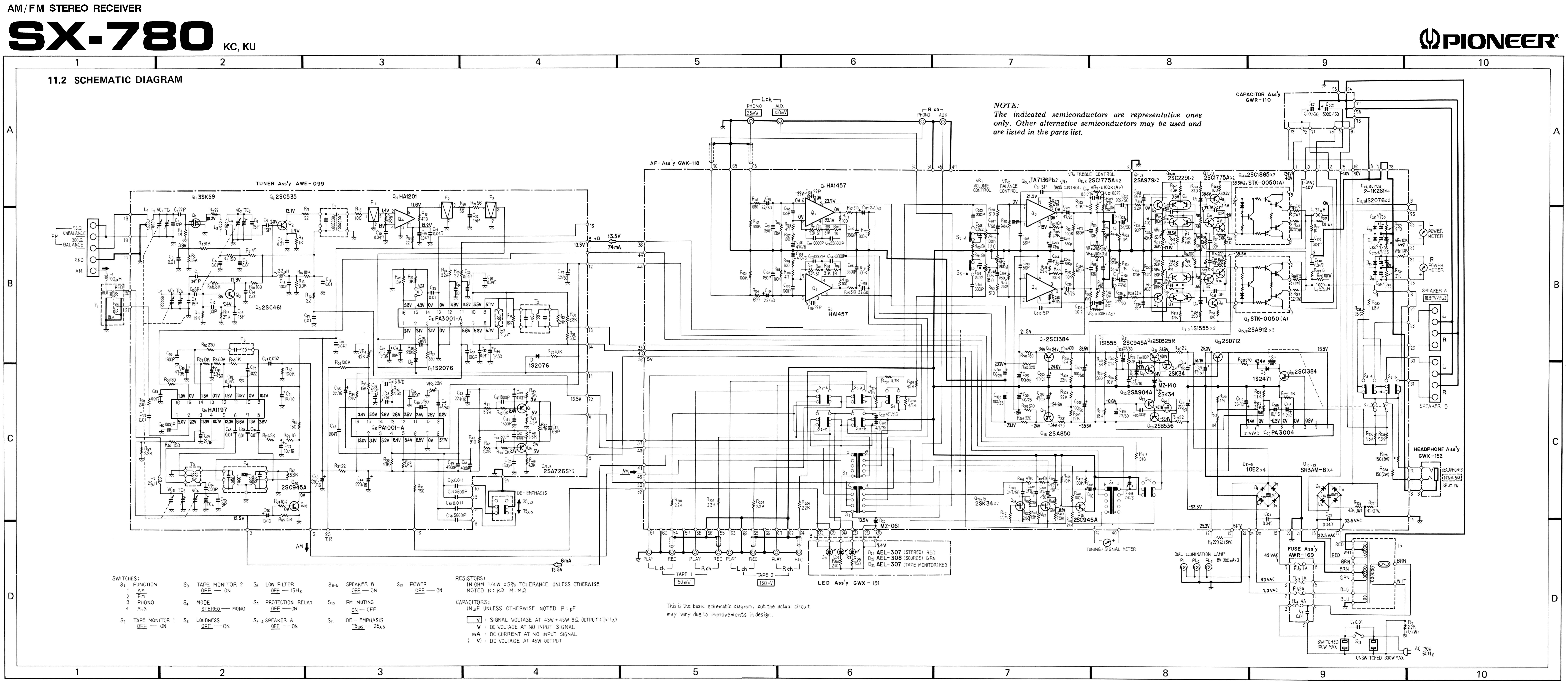
If you don't have a clean schematic, you can download this version:

SX-780Schematic-Wide.jpg
 
Thanks Watthour,
I'll tackle this in the morning. Just put a new battery in the Beckman and will follow your steps above.
Thanks for the schematic. I'll update tomorrow with results.
CS
 
Thanks everyone.

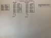
Watthour, I ran the meter tests and results are in the attached table. The fuses all tested good. The Q25 connections appear good. The diode tests I did carefully, but their results did not match, as you see in the table. Where to from here? Is their hope for it?
Test Table.jpg
CS
 
Neither of those look happy to me :(. There is hope :angel:
Have you seen this post?=> STK-0050 replacement for SX-780 and others
Lots of good info there, and I heartily recommend the hbrown/rcs16 custom discrete modules. Have used them myself. In an SX-780, and I have another on the shelf (actually floor) for after my SX-1050 is done.
This is how I check STKs, by not checking them at all, instead I check to see if the amp is good.
Get four resistors, same value, 220Ω to 1kΩ (not critical) and put them in the SX-780 (STKs removed) like this:

Pioneer SX-780 red dc-test.jpg

z-adamson.jpg

No speakers, input to Aux, no input, volume minimum.
Power up, check power supply voltages, then measure and record these voltages:

Left side:
STK Pin 1 on pcb:
STK Pin 0 on pcb:

Right side:

STK Pin 1 on pcb:
STK Pin 0 on pcb:

PCB
Pin 9 of pcb:
Pin 6 of pcb:

Voltages on STK pcb pins 0 and 1 will be about equal in voltage but opposite in polarity, positive and negative.

PCB pins 6 and 9 should be close to 0vdc, dc offset readings before the relay.

If these are good the amp is dc balancing and the STKs are bad. You can adjust the dc offset in this test condition. Won't play music though, no STK, no current gain.

If your power supply voltages are correct the protection relay will probably pull in. If not, this is a perfect configuration for TS & R.
 
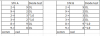
STK Diode Test.PNG
I ran the diode tests again with new battery in my Beckman meter - results above

Thanks Merlynski - this is getting a wee bit beyond my schoolboy physics, I could not build the custom STK replacements, but I will persevere with my dim bulb tester and the procedure you mentioned above.
I'll likely proceed also to order two eBay STK knock offs anyway as they are not big bucks. I'll keep this thread posted on my progress - give me a few days and thanks again.
CS
 
Last edited:
You are welcome!
You had also asked about testing the relay. The relay doesn't usually go bad, more likely the relay driver transistor (Q26) has gotten old and tired. Replace it with 512-KSC2690A (Mouser pn) If you do go with the KSC2690A you will have to enlarge the holes in the pcb, as the leads are slightly bigger. I keep a pin vise handy with a 1mm drill bit in it for just that purpose. Or you have another failure on the pcb and the protection circuit is doing its job correctly. If so then some troubleshooting is needed.
 
I have joined the Dim Bulb Society. Unfortunately my dim bulb is shining with the sx780 powered up. I guess it's "Houston, we have had a problem here" somewhere in the innards.

.Dim Bulb.jpg

Will continue later with Merlynski's procedures above in post #12 - waiting for resistors.
 
I have joined the Dim Bulb Society. Unfortunately my dim bulb is shining with the sx780 powered up. I guess it's "Houston, we have had a problem here" somewhere in the innards.

.View attachment 1839483

Will continue later with Merlynski's procedures above in post #12 - waiting for resistors.

Remove the STKs, they are the most likely culprit for the bright bulb, then test again. You can measure the power supplies on the full mains IF the bulb dims without the STKs installed. That will give you a bit more information about what is going on.
 
Today's update - removed the original STK packs. Power on with DBT shows no bright bulb light up after powering the amp via DBT. No audible relay click heard so far, however a barely noticeable click type sound can be heard after 5 secs or so with a screwdriver on the chassis and on my ear. Bad news is my Beckman meter has gone south, (it's about as old as the Pioneer), and so I cannot check any voltages. Currently waiting for new meter and more supplies including two replacement STK's all bought on Amazon.
CS
 
Today's update - removed the original STK packs. Power on with DBT shows no bright bulb light up after powering the amp via DBT. No audible relay click heard so far, however a barely noticeable click type sound can be heard after 5 secs or so with a screwdriver on the chassis and on my ear. Bad news is my Beckman meter has gone south, (it's about as old as the Pioneer), and so I cannot check any voltages. Currently waiting for new meter and more supplies including two replacement STK's all bought on Amazon.
CS
You are making good progress. :thumbsup:

Next step is check the power supplies and protection circuit with STKs removed.
Measure and post the dc voltages at the following locations:
(copy and paste list, add your readings after each line)

STK Pin 2 connection on PCB:
STK Pin 9 connection on PCB:
+ side of C314:
- side of C315:
Emitter of Q19:
Emitter of Q20:
Emitter of Q25:
Pin 1 of the PA3004:
Pin 6 of the PA3004:
Pin 8 of the PA3004:
Collector of Q26:
AC volts on Pin 7 of the PA3004:
 
Hey - I got my Beckman back - it was a bad internal contact for the screen. So powered up with DBT in series. No bright bulb after power up. Checked the voltages at the STK pick up points:

Left Hand STK voltage inputs (as viewed from front of unit)
@Pin 1 -38.6 V
@Pin 2 -34.3 V
@Pin 3 -0.0 V
@Pin 8 -0.0 V
@Pin 9 +37.8 V
@Pin 0 +38.5 V

Right Hand STK voltage inputs (as viewed from front of unit)
@Pin 1 -38.6 V
@Pin 2 -34.3 V
@Pin 3 -0.0 V
@Pin 8 -0.0 V
@Pin 9 +37.8 V
@Pin 0 +38.5 V

So that's it for now...

ps where is this +/- B post I read about in other posts? (e.g. "Measured 31V at B posts (-31 and +31).")

CS
 
My last post was out of sequence and written before post #18, thanks again Merlynski.

My relay is coming on I reckon - if I power on and listen to the relay via a screwdriver to my ear, I hear a low level electric hum and then a movement after 5 secs and a bigger level of electric hum.

I did also find the B+ and B- posts (duh!) and have +37.6 V and -34.1 V on the + and - of both.
However, I am kinda lost on this list as I'm not experienced enough to recognize these components.
+ side of C314:
- side of C315:
Emitter of Q19:
Emitter of Q20:
Emitter of Q25:
Pin 1 of the PA3004:
Pin 6 of the PA3004:
Pin 8 of the PA3004:
Collector of Q26:
AC volts on Pin 7 of the PA3004:
I can find them on the schematic, but finding them physically on the PCB....?
I can of course read the post numbers printed on the board - is that what I do?, match the post numbers with your component list, like post#19 is Emitter of Q19 ?

Will gladly test them if I could find them!

CS
 
Back
Top Bottom