• The move to the new server is done. There are some software and database maintenance updates in process. This has us passing the hat around to help out. We appreciate any donations. Seriously, even a dollar helps. The payment page may be found here - https://www.audiokarma.org/support.html

Voice of Music 815: 6v6 Push Pull amp.

HepGreg

Well-Known Member
Hello, tubeheads.

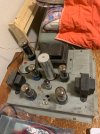
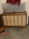
I've been on the hunt for a Magnavox push pull amp for a while, but this lovely piece came up for sale. A 1959 Voice of Music 815 console; 40 dollars and a 30 minute drive out to Washougal, WA from Portland got me this fine specimen:
IMG_1679.jpeg

IMG_1678.jpegIMG_1675.jpeg

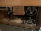
Turntable, Pre-amp/tone control & power amp; simple. no tuner.

still has all original V-M tubes, 5U4 rectifier, one 12ax7, and 2 pairs of 6v6GT. the couple i bought it from said it belonged to their mother or grandmother, and she was the original owner.

they used it and told me they had it serviced some time ago, for turntable issues. then it just up & quit on them. currently isnt powering on. i pulled the amp out of the cabinet, and took some resistance readings of the transformer, i think (?) there may be some issues with it, but this is only the second time ive done these tests on a transformer so im not sure how to interpret my findings:
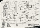

IMG_1683.jpeg
1. R across the plug (bridged): 1.2 ohm
2. plug to chassis: OL. / OL (no continuity)

3. R across primary: 1.6 ohm

4. R across 312v secondary: 89.6 ohm
5. R 312v to chassis: 46 / 43 ohm

6. R across 134v secondary: 38.9 ohm
7. R 134v to chassis: 19 / 19 ohm

8. 5VAC secondary (Blu/Wht): <1 ohm
9. Blu/Wht to chassis: OL / OL (no reading)

10. 5VAC secondary (Ylw): <1ohm
11. Ylw to chassis: OL / OL (no reading)

12. Unused Filament 6.3VAC (Blu): 1 ohm
13. Blu to chassis: OL / OL (no reading)

14. Filament 6.3VAC (Brwn): <1 ohm
15. Brwn to chassis: 61 / 61 ohm

does this seem like healthy transformer, or does it sound like its fried? those 5 & 6v secondary readings have me a little worried.
 
Last edited:
Register to hide this ad
I'm not sure what your numbers mean, for instance you list "10. and 11." as a 5 volt secondary, when the only numbers like that I see are the 10 & 11 on the preamp power socket that are the power transformer's primary. You will want to check the windings as they appear in the schematic, for instance on that socket you can check the 10 & 11 for the primary, the 3 & 4 for one of the 6.3 volt secondaries, and the 1 & 2 for the other 6.3 volt secondary. The 5 volt secondary can only be checked at pins 2 & 8 on the rectifier's socket and pins 4 & 6 of the rectifier will get you the HV secondary, with chassis ground being the HV's center tap. The checks must be done with the pre amp plug unplugged and the tubes out of the amp.

My guess will be that unless there is a big pile of wax under the transformer, it's likely ok, and that the no power issue will be found in something far simpler like the on/off switch.....
 
Nothing screams problem to me, but a dim bulb tester with no tubes will tell the tale for sure. Jumper pin 9 to pin 10 on the socket to complete the circuit.

Are you planning to run this amplifier stand-alone, or are you keeping it in the console? This has no complete feedback path or voltage amp on the chassis, so if you want to run it stand-alone its going to need a tube socket added to be properly useful.

On the upside it looks like you've got a nice 5v winding to use as a bucking winding if there is no tuner and it turns out the voltages run high. I like rectifier windings for this especially, they are high current and have extra high voltage insulation.
 
Wow, That 12AX7 was perfectly hidden.

Nice amplifier layout...

Yeah, The feedback leaves the chassis to be run through the tone controls.
 
Last edited:
I think the 12AX7 is between the cap and input cables, can't see it because of the pic angle. Its just a floating paraphase inverter in this, no voltage amp, no feedback path. Note the umbilical has a connection to the speaker output at pins 6 and 7. Fair bet if you looked at the preamp chassis you'd find another tube set up as the voltage amp with the feedback connections tied to those pins.
 
I'm not sure what your numbers mean, for instance you list "10. and 11." as a 5 volt secondary, when the only numbers like that I see are the 10 & 11 on the preamp power socket that are the power transformer's primary. You will want to check the windings as they appear in the schematic, for instance on that socket you can check the 10 & 11 for the primary, the 3 & 4 for one of the 6.3 volt secondaries, and the 1 & 2 for the other 6.3 volt secondary. The 5 volt secondary can only be checked at pins 2 & 8 on the rectifier's socket and pins 4 & 6 of the rectifier will get you the HV secondary, with chassis ground being the HV's center tap. The checks must be done with the pre amp plug unplugged and the tubes out of the amp.

My guess will be that unless there is a big pile of wax under the transformer, it's likely ok, and that the no power issue will be found in something far simpler like the on/off switch.....
sorry for the confusion, the numbers were just my bullet points for my list. i measured across each winding, and then from each half of the winding to chassis ground.all of these measurements were taken with the tubes out, & disconnected from the pre-amp.
 
Last edited:
Nothing screams problem to me, but a dim bulb tester with no tubes will tell the tale for sure. Jumper pin 9 to pin 10 on the socket to complete the circuit.

Are you planning to run this amplifier stand-alone, or are you keeping it in the console? This has no complete feedback path or voltage amp on the chassis, so if you want to run it stand-alone its going to need a tube socket added to be properly useful.

On the upside it looks like you've got a nice 5v winding to use as a bucking winding if there is no tuner and it turns out the voltages run high. I like rectifier windings for this especially, they are high current and have extra high voltage insulation.
i havent decided yet what i want to do with it, need to get some power to it first. i am aware of the missing gain stage & the feedback loop thing. there is room on the chassis to add another socket & complete the circuit for a standalone amp. i will jumper & try to power it up on the DBT today.
This schematic does not appear to match the amplifier?

I do not see two rectifiers or a 12AX7 on the amp chassis?

That usually means the Phase inverter is on another chassis or the amp is actually SE or there is a transformer driver or.. or...
there is 1 12ax7 on the chassis. the other one (not shown on this part of schematic) is on the pre-amp/tone control chassis.

IMG_1684.jpeg
 
Last edited:
Here's the Sams version of the schematic in pdf, which can be enlarged to view detail. The phase inverter is on the amp chassis and the preamp shows two 12AX7s. If yours only has one 12AX7 on the preamp that would indicate that the turntable uses a ceramic cartridge. Perhaps they made two versions?? The Sams version would use a turntable with a magnetic cartridge.

These are very nice sounding amps.
 

Attachments

Here's the Sams version of the schematic in pdf, which can be enlarged to view detail. The phase inverter is on the amp chassis and the preamp shows two 12AX7s. If yours only has one 12AX7 on the preamp that would indicate that the turntable uses a ceramic cartridge. Perhaps they made two versions?? The Sams version would use a turntable with a magnetic cartridge.

These are very nice sounding amps.
sorry, the pre-amp has 2 12ax7s on it. i assumed one was TT related, and the other was the first gainstage of the amplifier. i havent looked too hard at the pre-amp schematics yet.
 
okay, jumpered pins 9 & 10, powered up on dim bulb. all the tubes lit up, but my bulb was glowing & current was limited to around 100v.

with the just the rectifier & the 12ax7 in, DBT stays dim & current sits at 117v. plugged in one 6v6, and the DBT started to light up & draw excess current. tried another 6v6 in the same spot, same result. tried swapping tubes in different spots, same result.
 
Last edited:
what size bulb?

Can't do a single output tube in this. It relies on the current draw of both in the channel to properly bias the output stage. A single tube will just cook. If it powers up OK with the rectifier in though, that tells me the high voltage stuff is fine. Unlikely all of the outputs are bad, but highly likely the coupling caps are. The output tubes even when working properly are going to consume the bulk of the power in this so what you're seeing may be totally normal depending on bulb wattage. Fair guess it needs at least a 60 to make this go and even then its going to drop voltage. 100 would be better.

no RIAA stage in this, so it would be for a ceramic cartridge. First 12ax7 section is gain to compensate for the passive tone controls, second is voltage amp for the output stage.
 
what size bulb?

Can't do a single output tube in this. It relies on the current draw of both in the channel to properly bias the output stage. A single tube will just cook. If it powers up OK with the rectifier in though, that tells me the high voltage stuff is fine. Unlikely all of the outputs are bad, but highly likely the coupling caps are. The output tubes even when working properly are going to consume the bulk of the power in this so what you're seeing may be totally normal depending on bulb wattage. Fair guess it needs at least a 60 to make this go and even then its going to drop voltage. 100 would be better.

no RIAA stage in this, so it would be for a ceramic cartridge. First 12ax7 section is gain to compensate for the passive tone controls, second is voltage amp for the output stage.
the only bulb i could find at the hardware store when i built my DBT was 200w, so thats what i use. it doesnt light up super bright, the filament does turn orange though.

thanks for the insight about the coupling caps. i also tried with both tubes in each channel, with the same result.

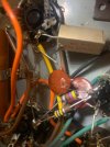
upon inspection, it looks like one of the .01uf caps is pretty cooked. got some bubbles on it:
IMG_1687.jpeg

the 0.22uf ones look okay. but ill start by replacing these 4 caps i think.
 
Last edited:
replaced C5 & C6, the 0.01uf coupling caps. i hooked everything back up to check it out, got power now. played an ipod through it, worked for fine for like one song. switched to the phono input, was greeted by an insane high pitched oscillation, full volume.

took the pre-amp out, cleaned the controls, put in a newer pair of 12ax7s. still screeching at me, now on all sources after it starts to warm up. bummer.

ill have to order the other coupling caps. im assuming the issue is in the power amp, seeing as the oscillation was full volume with the volume knob all the way down. is this a tell-tale sign of a specific problem to anyone?
 
Last edited:
Even if those are working today I don't trust them to keep working reliably.

Mind you I'm kinda guessing here, it may be something else but squealing sounds like some form of unwanted feedback. I doubt someone has been inside changing things around in a way that could produce positive feedback. Could also be some other failed cap. Paper ages badly and should usually be replaced just to keep everything happy
 
Open or high ESR power supply caps can do this. No decoupling between stages
I was thinking the same thing. The only supply bypassing for the entire pre-amp is the 20uF section C1 of the can.

Please check the can cap to see if it's getting warm at all- if it is, don't run it that way- a cap in the can could short, or explode. If the can is not getting warm, you could try tacking a spare electrolytic cap from the 200V to ground inside the amp chassis side as just a quick check.

Do you ultimately intend to use the pre-amp and amp together, or add a gain stage to the power amp and use it stand-alone?
 
i havent decided yet. just trying to get it working first, i originally bought it with the intention of gutting the amp, but i thought it would be a fun challenge to get it working as is first.
 
Back
Top Bottom