• The move to the new server is done. There are some software and database maintenance updates in process. This has us passing the hat around to help out. We appreciate any donations. Seriously, even a dollar helps. The payment page may be found here - https://www.audiokarma.org/support.html

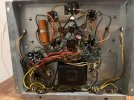
Voice of Music 815: 6v6 Push Pull amp.

Either way, you have some good parts to work with. I've always been a fan of Voice of Music, and this type of console amp is from what I hear a pretty good performer. Would make an attractive stand-alone. If it were mine, I would check to see if that hole for the chassis to chassis connector is about the same size as an octal socket- if it is, you could convert the 12AX7 into the gain stage, and use an octal 6SN7 dual triode for the phase inverters. Lots of help here whatever direction you want to go.
 
looks about the same size as an octal socket. its certainly bigger than the smaller 12ax7 socket. thats probably what ill do, if & when i decide to separate the amp.
IMG_1696.jpeg
 
Last edited:
something like this is an option


but physically thats really not a great location. I'd want the voltage amp to be as close to the phase inverter and input jacks as practical, not over by the power supply where all the noisy bits are. Looks like you could sneak it right between those two, though it may end up a little cramped.
 
it might be possible to squeeze a 9 pin in the space where that knockout is between the input jacks and the existing 12ax7 but it would be pretty cramped.

another option would be a pair of 6AV6 mounted roughly where each of those sand resistors is. They would sit between the input jacks and the inverter, but pushed outboard a bit towards the 6V6. 6AV6 is 1/2 a 12AX7 so electrically its the same, just physically a bit smaller.


if none of that works I'd rather put the 12ax7 in that blanking plate than where the umbilical socket is. Less going on over there, and you could easily build a box around it to screen out any noise if needed.
 
waiting for some parts to arrive, so im getting more familiar with the schematic. ordered a new can cap from Hayseed Hamfest, but it wont be here til april. i color coded the schematic to match the actual wiring in the amp, which always helps me a lot. also did the resistors & caps that ive replaced so far.

V-M815.png


gain_NFB stage.png

the yellow lines coming from the outputs to 6/7 on the plug are the NFB circuit. if i end up adding a tube to the chassis for standalone use, i think i would have to "pull" (figuratively speaking) this portion from the pre-amp & move it to the chassis, correct? would i need R25 & R26 as well? and 1/2 & 3/4 on the plug would be for the filament circuit. would it be better to use 1/2, that way each heater winding is heating 3 tubes?
 
It's going to be a little more complicated than that. First the easy stuff:

Installing a 12AX7 or the like in the power amp will be required as you understand. The two halves of that one tube will be the voltage amplifier for each channel. The filament can run on either winding as they are rated for it, but putting it on the 1/2 side makes slightly more sense (balance 3 and 3 as you indicated). This will leave the 6.3V filament in blue for the tuner unused, which you can put in series with the 117V primary winding to buck the voltages down so all of the filaments run at the correct voltage with the modern 122V wall voltage. (You did this on your last Magnavox build.)

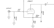
Referring to your attached schematic above, you will need plate (R27,28), cathode (R29,30), and feedback (R31,32) resistors as you know. Yes, you will also need grid stopper resistors (where R25,26 are shown), but they will be more like 10K rather than the 220K shown, and you will need to add 470K grid return resistors from the end of those stopper resistors to ground. The junction of the 470K grid return and 10K grid stopper will be the audio input or volume control if desired. This will end up looking a lot like the front end of Dave Gillespie's 8600 amp, shown in the schematic snippet below on the right.

Now, the harder stuff. Below on the left is a snippet of the .pdf schematic that was attached to post #9 that i will refer to- unfortunately it's part numbers do not align with the version you attached, so you will have to translate. The problem I am seeing is that this "AF AMP" second triode voltage amplifier as designed in the original VM pre-amp has pretty low gain, because of the 1500 ohm cathode resistor (R18), and the 47K plate resistor (R17). It was probably such low gain because the first triode preceding the tone stack has fairly high gain (losing some in the stack), and the two worked together to provide the total voltage gain needed by the overall amplifier. Not a huge problem, we just need to modify the plate and cathode resistor values to increase the gain of this single stage tube, which in itself is pretty easy. The complication that it introduces is that by changing the gain, you are then forced to also change the feedback resistor, to a new value that provides the correct amount of negative feedback that will be required for a stable amplifier of sufficient sensitivity. Not insurmountable, but you will be forced to start with a safe value, then adjust that feedback resistor in final tuning to a level of sensitivity that feels right, and is still stable (not oscillating).

I tend to be in Dave Gillespie's camp when it comes to this part of amp design- build an amplifier with a LOT of (open loop) gain, then tame that back considerably with a lot of negative feedback, which results in wide, flat bandwidth, and low distortion. To that end, I really like the triode gain stage of the 8600 as shown on the right. Notice the plate resistor of 470K is 10 times that of the one on the left. This is a very high fidelity choice providing a very flat linear load line with high gain, but it must be biased up correctly. The cathode resistor will need to be a smaller value for high gain, and while the 820 ohms is not that different from the 1500 on the left, the larger plate resistor will force a much lower bias current, so to get a workable cathode voltage the 150K "cathode pull-up" resistor on the right is used. This is absolutely ingenious, because it allows a smaller cathode resistor by dumping several times more than the bias current down through the cathode resistor, which elevates the cathode voltage to the necessary ~1.2-1.5V, stabilizes the bias current and the cathode voltage despite tube variation, and gives quite excellent performance.

If you like that front end, all we would need to do next is start chewing on a good starting value for the feedback resistor that will put you in a good initial landing zone, and we can walk it in from there. There are other ways to do the front end, lots of ways of increasing gain and setting the bias, and I'm sure others will suggest alternatives. Either way, feedback will need to be tweaked, and I don't think you will be happy with the sensitivity of the amplifier with that original gain stage as designed.

1773652150408.png 1773652233891.png
 
Thank you, @HepGreg for the kind words.

I did find some credence for the suggestion by @gadget73 that you initially build the front end as designed- In examining more closely the phase inverter that is on the amplifier side, it's using a 47K plate resistor as well, and is arranged surprisingly as a floating paraphase, oddly split in half with the voltage amp side over on the pre-amp half, but using different values of coupling capacitor. I missed that in my initial assessment. Generally the voltage amp and inverter will both use the same plate resistor and the two sides generally need to have similar modifications to work together properly. I still believe that when moving the voltage amplifier to the chassis, there will be opportunity to increase gain significantly and perhaps make other optimizations.

There some other changes to the amplifier that are strongly recommended:

1. Buck the primary. A very simple connection, runs filaments at the correct voltage. (Not needed in stock designs when voltages historically ran as low as 110-115V but necessary now)

2. Add a filter choke to the power supply- This is an example of VM just being cheap- Some hum from supply ripple was common in these consoles, and tolerated because the sources were noisy, the speakers wanting, and the amp was never required to put out a lot of output power so the almost unfiltered B+ power supply was tolerable. Here it is not. I recommend an inexpensive P-T156R, 1.5H, 200mA, 56 ohms, about $24.

3. Larger cathode bypass capacitors for the 6V6 pairs. This is an area Magnavox and many others scrimped on because larger capacitors were expensive. 40uF across 200 ohms gives a 3dB (1/2 voltage) at 20Hz, which means it begins to roll off at more like 60Hz. This should be more in the ballpark of 100uF at least, and I like to use 50V or greater for the current capacity.

4. Screen stopper/isolation resistors- Dave G did this with the Magnavox 8800. When you have separate cathode resistors/capacitors for each channel, the screen supply should be separated as well to avoid oscillation. This is easily accomplished by putting a 68 ohm resistor in series with the screen supply for each channel as shown in his schematic.

5. Be prepared to make a minor adjustment to the cathode resistors- and possibly consider using adjustable bias pots. This is another classic 6V6 design where they spank these poor tubes like a rented mule. (They can take it, they are concert-rated rock stars but they do have limits.) They are running at a really high plate voltage, then dropping the screen down so that the tubes are basically right at the maximum plate power limit. (This is again why it is prudent to buck the primary so you're not adding additional voltage atop the design value. However, by adding the choke, the plate and screen voltages will also be slightly higher, so once you get the amp up and running with your modifications, it would be prudent to look at all of the power supply, plate, and cathode voltages and see if we might want to make some tweaks there.
 
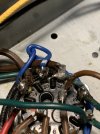
jury is still out on turning this into a standalone amp; but i more than likely will at some point. i just routed the bucking winding (twisted blue pair):

IMG_1706.jpeg

still waiting on the .022uf coupling caps in the mail. i snagged a pair of sprague caps from work, but one ended up being 0.0022uf, so i need to swap that back out for the right value before i turn this thing on again to confirm wether or not the can cap is bad or if somehow the coupling caps were to blame for the oscillations i was getting.
 
Stand alone amps are very nice forget about any controls like volume, bass, treble muilti control for turntable, ect. get yourself a nice pre amp and go right to this Stand alone. I have 5 from Stromberg Carlson they push my Altec Lansing 15' three ways to serious volume at 12-15 watts a side 6v6gt tubes I find the best tubes 6v6gta sylvania black plates. take you time the best is to study the schematic often...get yourself schematic so you can follow the wires from the amp to the control pre amp study that well look for the power to and from the pre amp of it normal, to the stand alone amp. that's where a fuse, on and off switch, look for the output transformer wires you need to place in the back to put in a left the right. very cheap cost for the items. yet when you get it done and power that baby up i remember mine first time i was WOW is that really something i did.. i don't mean to affend you if you know who to do basic electronics repair and diagnose . the very best to ya enjoy your amp. don't hesitate to ask questions... don't do any work until you have the parts and understand it.. if i can give ya any help ill be looking for your stand alone Voice of the music title..
 
@fxer1982 i built a DG-SE1 a little while back from an 8600 magnavox. i run it with a restored PAS-2 pre-amp. i will eventually, most likely, convert this into a standalone amp. i just wanna get it working again as a full console, for the learning experience before i decide to gut it.
 
alright, put the 0.022uf caps in. set everything up in the cabinet, plugged the amp into the DBT. turned on the DBT, and the bulb lit up before i even turned on the amp, and current was limited to around 95-100v. which means i think i may have wired my buck incorrectly, does this look right? i used my DG-SE1 as a reference & i swear this is how its set up.

left to right: 9. Wall plug/secondary, 10. Primary/secondary, 11. wall plug/primary.
IMG_1744.jpeg


edit: i used a jumper to connect 10 & 11, and i get continuity between the prongs of the wall plug. so im assuming its wired right... cant imagine why it would cause the bulb to light up before powering on.
 
Last edited:
I'm sorry @HepGreg -

Your picture shows the blue spare filament winding connecting to pins 9 and 10 of that connector. This should be correct from the schematic you have posted, so there is more going on here somewhere. Where is the switch? I don't see it in the schematic?

1774204507614.png
 
the power switch is the source selector on the pre-amp.

IMG_1746.jpegIMG_1676.jpeg

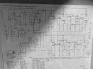
sorry for the terrible photo of the pre-amp schematic, ill try to take a better one today.

i got some input from a Voice of Music group on facebook, a few people told me that the oscillations can be caused by mismatching the channel A/B rca plugs inside the cabinet. so im hoping that's what happened when i initially hooked it back up & got that terrible noise out of this thing. but now i need to sort out whats going on with this dim bulb issue first. oye. i can see why people dont like working on consoles these days.
 
Last edited:
Since you did not mention you are still trying to use this connector with the pre-amp. If you do, the blue winding between terminals 9 and 10 are completing the circuit rather than the switch, that is why you see the set turn on before the switch is. The switch when turned on will then short out the blue winding! Very bad.

To do this mod =and= use the pre-amp, you have to disconnect the black primary winding from pin 10, and connect the blue winding between the black that came off of 10, and pin 10- so the blue winding is in series with the black primary. If the filament voltages run higher than before, reverse the polarity of the blue winding so the filament voltage is lower than before.
ahhh-ha. sorry i failed to mention that. i didnt power the pre-amp on while it was on the DBT, so im hoping nothing was shorted.
so basically i need to connect the blue secondary in between the black lead from pin 10, and pin 10. and if the filament is too high, reverse the blue leads.

i also realized, there is this (i think) wirewound resistor connecting pin 5 & 8 on the rectifier tube:
IMG_1747.jpeg

says "ohmite 150" on it. measures at 156.7 ohms. this is not in the schematic, but it would be sitting at the junction dot between the yellow 5v secondary & C1/R5. is this being used to choke the power supply?
 
Last edited:
Back
Top Bottom