• The move to the new server is done. There are some software and database maintenance updates in process. This has us passing the hat around to help out. We appreciate any donations. Seriously, even a dollar helps. The payment page may be found here - https://www.audiokarma.org/support.html

Voltage Doubler Power Supplies

TriodeLuvr

So many electrons, so little time!
Subscriber
Through the years, I've found that push-pull amplifiers with solid state voltage doubler power supplies generally have an edge in terms of dynamics and impact over their "standard" cousins. It's been frequently suggested to me by others that that this is due to the superior regulation of this type of power supply.

I'm currently in the process of "re-creating" a vintage amplifier that uses a voltage doubler power supply. The project consists of a modified 35W/ch amplifier section and power supply from a 1960s AM/FM receiver. I finally had a chance earlier today to examine the power transformer in more detail, and despite knowing that the resistance of a doubler transformer should be lower than others, it caught me off guard. When I measured the DCR of the HV secondary, I was expecting to see 50 or 60 ohms or more. Instead, the HV winding is less than four ohms. That's right - four ohms. I was so surprised by this, I connected a variac to the primary, just to be sure the secondary isn't shorted.

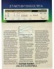
Some time back, I also came across the following text in a spec sheet for a Harman Kardon Chorale A260. This is a 30W/ch integrated amp with a doubler supply. I thought the spec was marketing BS at the time, but now I'm not so sure. I'd be interested in hearing any opinions on all this from anyone else who is working with voltage doublers. Incidentally, I have several of these of various models to rebuild. I'm hoping to have time to post descriptions and pics of each project as they progress.

Jack

A260 regulation.jpg
 
Last edited:
Register to hide this ad
A voltage doubler, primarily due to the lower impedance of the secondary winding in the transformers used for such purposes, usually has a lower output impedance, compared to a "standard" full-wave rectified power supply. That lower impedance can definitely make for better dynamic response (less "sag" under load).

Regards,
Gordon.
 
Voltage doubler supplies produce twice the ripple as the same supply with a full wave center tapped transformer configuration. This usually isn't a problem though unless you do crazy stupid things with the filtering.

I can believe that spec sheet text to a point. The 1% regulation number quoted of course depends on the amount of current the power transformer is rated for relative to the max current the output stage will draw at full power. Also I have found that many of these types specs are quoting a single channel being driven even though in real life both channels would be driven.
 
NOTE: Edited for accuracy (corrected error of memory, after consulting notes).

I have built amps, that managed to have power supply sag of 1% or less. My Eico ST70 "Hot Rod" monoblock amps, using reissue Fender Twin power transformers with bridge rectifiers (low drop diodes, 330uf with 0.1 ohm ESR first supply cap) only dropped 4.5V for a nominal 465V B+, between idle and full load (467.5V to 463V).

With a full-wave rectifier and a low-impedance transformer (20 ohm secondary), with the same type diodes and similar PS capacitance (dual 220uf caps in parallel, each with 0.2 ohm ESR) it was about 11V drop, from 460V to 449V, between idle and full power. That's about 2.5%. However- that was BOTH stereo channels on one power transformer- it would have had less drop, as a monoblock (less draw on the PT).

It's all about low impedance in the power transformer, power supply components that also don't have excess resistance, and sufficient (not excessive, but enough) capacitance...

Regards,
Gordon.
 
Last edited:
Voltage doubler supplies produce twice the ripple as the same supply with a full wave center tapped transformer configuration. This usually isn't a problem though unless you do crazy stupid things with the filtering.
When you say "same supply," can I assume you mean a supply having the same amount of filter capacitance? Each capacitor in a doubler passes 60Hz ripple current, not 120Hz as in a FWCT or FW bridge. Based on this, I would expect capacitors in the doubler to be less effective as filters. They should be just as effective in terms of the supply's output impedance though.
I can believe that spec sheet text to a point. The 1% regulation number quoted of course depends on the amount of current the power transformer is rated for relative to the max current the output stage will draw at full power. Also I have found that many of these types specs are quoting a single channel being driven even though in real life both channels would be driven.
You might be right about this being a single-channel spec. Also, the regulation spec improves when zero-signal current is set relatively high, so that zero-signal to full output results in less average current change. I don't remember the bias current in the A260, but it's another of the amps I'll be reworking.

Jack
 
I have built amps, that managed to have power supply sag of 1% or less. Not just doublers- the Eico ST70 "hot rod" amps I build with KT88s, also manage to do that, with a standard full-wave secondary and rectifier diodes That's less than 4.5V drop, on a 450V B+, at full power, compared to idle B+ voltage.

It's all about low impedance in the power transformer, power supply components that also don't have excess resistance, and sufficient (not excessive, but enough) capacitance...

Regards,
Gordon.
I've never seen a standard B+ supply that was capable of 1% in a class AB1 amplifier. Assuming this isn't being accomplished by simply moving idle current toward class A, I would certainly be interested in the component values (and the power transformer specs) that make this possible.

Jack
 
Let's do a thought experiment. Imagine a power transformer wound with half the winding window filled with the primary, other half with four wires in parallel. This is all the copper that fits. Let's say primary is 1 Ohm, 120V and each of the secondary windings is 4 Ohms, 120V. Now we connect those secondaries in parallel for a voltage doubler, series-parallel for a full-wave bridge, all in series for a FWCT. Caps are 1000uF with 1 Ohm ESR, and we're going to load this at 600 mA. Doubler produces 301V with 10.8V of ripple. Full wave bridge, with same caps connected in series, produces 307V with 11.3V of ripple. The difference is due to the extra ripple current in the doubler - without the effect of ESR, they'd be identical. Transformer windings are dissipating 12 watts in both cases, gonna be warm!

And full-wave center tap - 299V with 10.5V ripple, but the transformer is dissipating 17 watts - we're going to have to back it off, this transformer is not going to deliver as much power in this configuration. Regulation (with good enough caps) will be the same for full wave bridge and doubler, FWCT will be worse - it can do about 80% as much power out of the same transformer size.

So conclusion: don't use FWCT if you have a choice, lower output rating or worse regulation. Also needs diodes with twice the PIV rating. With modern caps, doubler can perform very close to full-wave bridge - I used unrealistically high ESR number to magnify the difference (first 1000 uF Nichicon cap I looked up was 0.2 Ohms). Caps have slightly higher ESR at 60 Hz than 120, and ripple current is higher in doubler too - but use enough capacitance and it's not an issue.
 

Attachments

  • PSU.jpg
    PSU.jpg
    154.5 KB · Views: 45
Thanks Tom, you went to a lot of trouble to provide that info. I hadn't compared the different configurations at such a detailed level, primarily because all the amps I'm reworking have doubler transformers. The other configurations aren't an option. However, I have run this through SPICE and have developed a CLC configuration that I believe will work well. Ripple is well controlled, series DCR is minimal and the output impedance is low. I recently discovered that the design and the values are nearly identical to the supply in the McIntosh MC240, although I didn't copy from that. This will be something of a learning experience for future builds, several of which will use EL34s in straight pentode mode (the current project uses 6L6). My plan for powering the screens of those tubes requires primary B+ to be as well regulated as possible. I have not been able to find a commercial example of this topology - doubler PS feeding pentode EL34s. It appears I might be breaking new ground in this respect.

Jack
 
Not sure why but voltage doublers often seem to be talked down on as being somehow inferior to other designs. The stuff I have with doublers works extremely well. Everything I have with silicon rectifiers has much better regulation than any of my tube rectified stuff.
 
I've never seen a standard B+ supply that was capable of 1% in a class AB1 amplifier. Assuming this isn't being accomplished by simply moving idle current toward class A, I would certainly be interested in the component values (and the power transformer specs) that make this possible.

Jack

Actually, I went back to my notes- the full-wave one was about 2.5% (11V drop).

The ones I did with Fender Twin reissue power transformers (bridge rectifier), did do only about 4.5V drop.

Message above corrected!

Regards,
Gordon.
 
Actually, I went back to my notes- the full-wave one was about 2.5% (11V drop).

The ones I did with Fender Twin reissue power transformers (bridge rectifier), did do only about 4.5V drop.

Message above corrected!

Regards,
Gordon.
Those are still excellent numbers. I think the 36W Marshall clone I built recently with a FWCT power supply was about 8% drop at full output. Difficult to compare though, because it used a 5AR4 and much less capacitance then most doublers.

Jack
 
Not sure why but voltage doublers often seem to be talked down on as being somehow inferior to other designs. The stuff I have with doublers works extremely well. Everything I have with silicon rectifiers has much better regulation than any of my tube rectified stuff.

Doublers have been used in some of the world's most highly respected tube audio gear, including HK Citations and McIntosh. Now, however, it seems you can't even buy a suitable power transformer off the shelf. And there seem to be many misconceptions in the DIY community about doubler PS characteristics. Just look at this thread, where someone says, "They have very high output impedance," and another poster says, "...voltage doublers are OK for low current."

https://www.diyaudio.com/forums/tubes-valves/76220-power-transformers-decisions.html

Ironically, the amp I'm building now will use a doubler for B+, but a FWB for the bias supply. Maybe this topology simply isn't well understood, or maybe hi-fi design has been polluted by philosophies used in building instrument amps. I don't recall ever seeing doublers in any major guitar amplifier brands, although there might be a few somewhere.

I'm surprised HK didn't take better advantage of this concept in their marketing materials. It wasn't until much later, in what I would call HK's second era of SS offerings, that they began to advertise "high current" capability. The 580i receiver was an example of this, and I've often wondered if the products from that era and the earlier tube amps were inspired by a common design philosophy.

Jack

HK 580i Ad.jpg
 
It's hard to find doubler- compatible transformers- but it's not hard to find bride-rectifier-compatible ones with comparable performance. Take the Fender Twin 1965 Reissue power transformer from Hammond (the 290EBZ, IIRC)- 340V, single low impedance secondary winding. Makes for 450V B+ with enough current to run two stereo PP 6L6 or EL34 channels, or a single channel of KT88/6550.

If you want to be clever- another trick is to find a transformer from a solid-state amp- something like a 75-0-75 secondary, which would be common in a 200w/ch solid state amp. They have to be low impedance, as the speakers are basically run directly off of the B+ voltage without any step-down. Many times, they will be low-single-digit secondary impedance, even through the entire secondary. Wire it as a single 150V or so secondary (cap off the center tap). Voltage double that, and you wind up with somewhere around 390 to 400V B+. Just use a separate heater transformer, and if needed, a small transformer of appropriate voltage for bias...

Regards,
Gordon.
 
Yeah, I only like to use tube rectification, in amps that are very close to, if not purely, Class A.

They work pretty well for single-ended amps, those of which are inherently Class A. However, I even tend to use SS rectification on Class A2 amplifiers- because, as you start to draw grid current, the total current draw increases a bit at high amplitude.

Everything else gets as low of a power supply impedance as I can engineer.

Regards,
Gordon.
 
It seems like the presumption for this thread is that there has been a noticeable difference in audio perception due to a particular B+ generation scheme in a valve amp.

There was one sort-of-scientific comparison of a guitar amp which had its power supply altered in a way so as to preserve the B+ characteristics (including sag) but allow an apples-apples comparison by a group of people between when the B+ had normal default ripple, and when it didn't have ripple. The subjective outcome was that the 'ripple-less' characteristic lacked appeal (ie. more sterile).

I guess there may have been similar comparison 'tests' on hi-fi equipment where a well known amp was auditioned as default, and perhaps either had ripple suppressed, or enhanced - but that may need trawling through more scientific journals like Audio Eng Soc. But I guess the tough objective aspect is to retain all but one characteristic of a power supply, given the level of interaction between characteristics.

It seems like the characteristic at play here is not just ripple per say, but sag due to signal amplitude variation, where the signal output has not only amplitude change due to a change in B+ level (at a frequency below mains), but also a ripple level change during any such amplitude change, as well as secondary affects such as the fundamental frequency or step of the amplitude variation then incurs harmonic distortion (perhaps as the amp has lowered feedback or other resonance characteristics at frequencies below mains).
 
Last edited:
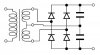
When it comes to raw power supply regulation, a proper voltage doubler scheme cannot be beat by any other conventional rectifier design. In the Ed Jahns years at Fender, nobody knew how to get more power out of a vacuum tube than he did. The man was instrumental in the development of the original 6550 tube while working at Tung Sol, and equally instrumental in the development of the GE produced 6550A while working at Fender. His choice rectifier configuration at Fender was a true full wave voltage doubler design, employing a bridge rectifier and CT on the HV winding that connected between two series connected caps on the output of the bridge. With this configuration, you could disconnect either one lead at either end of the HV winding (causing it to then operate as a conventional full wave voltage doubler), or the HV CT lead (causing it to then operate as a conventional bridge rectifier), and the output voltage would not change. But fully connected, the best of both worlds are achieved, by maintaining the very low impedance of a doubler configuration, but converting the 60 Hz pulses normally applied to each cap in conventional doubler design to 120 Hz as in a bridge configuration. All else being equal, it also reduces the internal impedance of a conventional voltage doubler power supply even further: In his power transformer designed for generating 135 watts RMS from 4 6L6 tubes (which it will do), the DC resistance on each side of the HV winding CT, is just 3.0Ω! -- equating effectively to 1.5Ω since it is truly a full wave design. This configuration dumps the maximum possible amount of current into each doubler cap, providing maximum raw supply regulation in the process. And of course, the ripple from such a supply is of a different nature, and easier to filter as well. This configuration is most often seen used in dual (+/-) power supplies of high powered SS amplifiers, but is used slightly differently in Fender's application since the output is not balanced relative to ground like it is in +/- SS applications.

Regarding the ripple from conventional voltage doubler supplies, manufacturers like Mac and H/K also used a choke to help filter the doubler's ripple before applying its output to any of the amplifier circuits -- output stage included.

Dave
 
Dave, do you have the schematic of this PS somewhere? This is interesting and would like to know more about it.
Thank you,
Brice.
 
It's this:

Doubler Bridge PS.jpg

It filters more efficiently than the "standard" non-center-tapped doubler because ripple current through the capacitors is 100/120 Hz.

Jack
 
Back
Top Bottom