Here's some commentary on chokes and doublers I've previously posted in dribs and drabs, edited together to remove the redundancy. It's drawn from some notes I had assembled for a book I never had the time to finish. I hope this explains why no free lunch exists with a double configuration as opposed to a standard full-wave or bridge rectifier, why transformer loading must be considered, and why chokes must be carefully chosen based upon the load in order to prevent damage to, or destruction of, the power supply.
Double Functionality
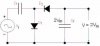
The voltage doubler splits the input current into two segments, call them Positive and Negative, with the load connected across the two segments. During each half of the AC waveform either Positive or Negative separately charges its associated capacitor (CPositive, which I'll abbreviate as CP, or CNegative, which I'll abbreviate as CN), but only does so during that half cycle. Each capacitor (CP or CN) therefore draws the entirety of its charging current during its associated half of the full AC cycle.
The AC cycle then turns into a pulse of current to charge CP, then a pulse of current to charge CN, and the process endlessly alternates. While CP is charging CN is discharging through the load, and while CN is charging CP is discharging through the load.
The overall current output of a doubler output has a waveform roughly identical to a non-doubler, but the load (current draw) on the rectifier tube or solid-state diodes and transformer are very different, and the peak current for each half during the charging cycle is much higher for each half than for a traditional full-wave or bridge rectifier configuration. What happens in the doubler is equivalent to a double half-wave rectifier configuration. This is key, as it has implications for transformer heating, ripple current, etc. Voltage doublers are problematic because the configuration truly is a dual half-wave, as the winding halves of the transformer are separately used.
The double half-wave is why ripple current is twice mains frequency, why regulation is poor under heavy loads, why the form factor (see below) is high, and why the de-rating can be twice what the form factor would be on its own. The peak charging current can be quite high which is why current must be reduced. The additional ohmic heating in the capacitor from the high dI/dt charging cycle is also why capacitor ESR matters in such a configuration.
The ensuing pulse from a half-wave tends to stimulate the tanks created by the transformer's parasitics, so the transformer will ring. Snubbers can fix that, of course. I've elsewhere posted about Mark Johnson's Quasimodo and Cheapomodo to determine the snubber values to remove the ringing which adds noise into the system.
Chokes and Multipliers
Adding a choke is not always straightforward.
To elaborate, and somewhat simplify, an inductor (choke) used in a power supply essentially is a means to store and release current by converting between voltage and magnetic flux. The choke therefore performs smoothing by absorbing pulsing DC from the rectifier and releasing it steady state to maintain the voltage at a certain level. The issue occurs when the flow of current is insufficient and the inductor saturates and then passes the full input voltage without any regulation or has the voltage climb because the collapsing flux generates voltage which has nowhere to go.
Like any charge pump, a voltage doubler is, by definition, capacitor-input. Two half-wave rectifiers alternately charge two separate capacitors with different polarity voltage. Such charging requires the positive/negative waveforms created by the rectifiers.
Adding a choke between the secondary and rectifier, typical placement in a conventional choke-input supply, unfortunately introduces DC into the transformer secondary, and the polarity reversals of the AC cycle prevent proper choke function.
A choke, however, may be used to stabilize the voltage under load in a voltage doubler by proper placement after the charging capacitors. The problem with such a configuration is that the regulation of a voltage multiplier falls as load increases because each capacitor is only charged during a half-cycle, so large chokes would obviously load the circuit and voltage drop would ensue. The voltage drop must therefore be accounted for in the design.
The advantage of using a small choke with a high DCR falls in the area of regulating and dissipating excessive voltage, i.e. critical inductance as below explained. A resistor could also do this, true, but it would not, as with the choke, regulate via energy storage and release.
As I have repeatedly cautioned, charge pumps (voltage multipliers) suffer from poor voltage regulation and have problems under heavy load or varying load. Transformers with multipliers similarly have poor regulation unless this is specifically addressed. I suggest considering the effects of adding a choke and additional capacitance after the capacitor bank to stabilize the voltage under load or sag will result. Remember, a Class AB amplifier has varying load. This means the voltage will bounce up and down. A Class A, however, is constant. That is why doublers typically are used only in preamplifiers, as those circuits operate as Class A and thus do not have the issue of sag from varying load.
In Class AB, however, the fast moving transients require rapid response or distortion results. In the old days voltage regulators required multiple tubes and were expensive. I have a tube regulated power supply with no ripple which was contempaneous with the the Dynaco ST-70 but at three times the cost. Pricey. Rather than use tube regulators, big chokes were combined with large filter capacitors. The regulation attainable by the amplifier designer was thus limited by expense, primarily for the choke although large electrolytics were at the time expensive. Modern supplies replace the CRC or CLC filter with a voltage regulator, as it rapidly increases the voltage to prevent voltage drop from current peaks. This appears to the load as a low-impedance supply, unlike the multiple stages of RC or LC filters.
Some complexity occurs, however, when the B+ for a Class A preamplifier is drawn from the same B+ used for the Class AB output tubes. Modulation of the supply by the Class AB output may modulate the Class A preamplifier circuit, causing distortion.
Choke "Critical Inductance"
A properly designed choke supply can have wonderful regulation under varying load. But the key issue with choke filters is critical inductance. This is a dangerous parameter which is poorly understood and consequently is honored more in the breach.
Consider how an inductor functions: core flux stores energy which is then converted back into current (movement of electrons through the circuit to reach the other side of the inductor) as needed. As flux increases the inductor's core (typically laminated iron for larger chokes and ferrite for smaller ones) increasingly moves towards saturation, i.e. the point where no more flux may be built. As core saturation increases the inductance decreases because the inductor is less and less able to absorb the new energy being passed through it, and thus increasingly behaves like a straight wire, passing the additional current unfiltered because it simply cannot be absorbed.
This is where the danger comes in. If (when) the load drops below a certain point the filter (inductor) saturates and becomes unstable: the unfiltered voltage then climbs to dangerous levels which can blow up capacitors and downstream components.
So, to summarize, the "critical inductance" addresses the minimum load on the inductor (choke) to maintain current flow through the inductor and thereby remain stable and regulating. If the load is too small, the inductor saturates and passes current like a straight wire. The voltage then climbs, often to dangerous levels. This is why one cannot hang a giant choke off a power supply and simply solve the problem of supply regulation; the choke must be properly sized for the load. Hams sometimes blow up power supplies in linear transmitters because the value for critical inductance was not met.
Form-Factor and Transformer Loading
The output current of the transformer must be de-rated since no free lunch exists when it comes to multipliers. This is the hidden parameter not often observed in power supply design.
A voltage-doubler configuration is equivalent to a double half-wave rectifier. Each half of the voltage waveform, in consequence, draws the entirety of the current during one half of the AC cycle. That really hammers the transformer. The half-wave rectifier's form factor is terrible for this reason and the transformer must be accordingly de-rated for heating. So it's actually worse than merely halving the current because the transformer is not ideal.
The term for the load from the rectifier is called "form factor", and was worked out roughly 125 years ago. The form factor is Irms / Iavg or Vrms / Vavg. So for a half-wave it is π / 2 = 1.5708. while for a full-wave it is π / (2√2) = 1.1107. Comparing the two ratios yields that the half-wave therefore places √2 = 1.414 greater peak current demand on the transformer than does the full-wave.
Since the transformer eddy currents and ohmic heating depend upon current, that difference may matter. It comes down to how robust the transformer is, and how much current is being drawn vs. the design limits. So if the transformer has a bit of headroom, i.e. already de-rated, then it's fine, more or less, in terms of heating. But hitting the transformer with a pulse of current demand may stimulate it to ring, since the parasitic inductance and capacitance form a tank circuit. A snubber may be needed. I note that a similar problem is posed by diode Qrr.
The de-rating factor for half-wave rectifiers is well understood. The theoretical peak current available from the doubler compared to the full-wave is (1 / √2) x Imax = (1 / 1.414) x Imax = 71% x Imax.
The practical current, however, is far less because core heating is somewhat greater in practice, given that the current draw of the double half-wave has √2 higher peak current than a standard full-wave and the ohmic heating is (I^2 x R). This heating must be dissipated into the windings and the core, so about 50% of the rated current for a full-wave configuration would be considered safe. But, again, the transformer must be designed for the higher peak current or the de-rating factor must be increased, so it's not a hard-and-fast rule. A transformer designed for a doubler uses a larger core to better dissipate the secondary heating.
Which leads us to...
Transformer Winding Limits and De-Rating
The winding's wire gauge, furthermore, was carefully sized for a particular current load because a transformer is money and mass in solid form: copper wire and steel laminates. So the designer at the transformer manufacturer carefully kaizened the designs to be just enough to deliver the rated current and not fail, and no one electron more. Any extra would have increased cost to the customer or eaten into the manufacturer's meager profits. Transformers are well known for failures because of over-current situations. For example, Heathkit had a power transformer which failed because the inrush current was not properly taken into account and the heating eventually burned out a winding.
The original specification may also have been sized for fluctuating current demands, so the steady-state current rating would be far lower.
One of the problems with overheating transformers is the wire will have higher resistance at any nick or kink, so that point will greater heat, and thus will eventually burn through. Similar problem with light bulbs where current is forced through a high-resistance weak spot (nick, kink, or other defect), overheating it and vaporizing it, until failure occurs. Metal migration and vaporization and all that.
Transformer windings they do burn out if stressed from high current peaks, Consider the effects of conduction angle upon transformer (and rectifier for that matter) load. As dI/dt increases, such as from a large capacitor, the resistance of the winding becomes more and more important, as the ohmic heating increases as (I^2 x R). A standard half-wave rectifier passing the same current as a full-wave rapidly overheats a transformer, and the diode must be higher rated.
The winding can only tolerate so much current at any given time, and this is why transformers are differently built for half-wave vs. full-wave, including doubler configurations. The literature from the transformer manufacturers specifies the form factor because it's a way of specifying the peak current.
The instantaneous current for a half-wave can be high enough to burn out a winding whereas a full-wave would not have any problem. It can also stress the filter capacitor, particularly electrolytics which do not well handle ripple current. This is why a conventional half-wave rectifier configuration must considerably de-rate the transformer. Transformer manufacturers typically supply a de-rating table for both rectifier configuration and load type (inductive vs. capacitive).
The correctness of the math I above set forth may be trivially verified in any basic textbook for electrical engineering. It really is about 71% maximum theoretical value, and since we live in the real world it would be best to not treat that as a proposed starting point. Keep it to 50% to 60% and the transformer will outlive all of us. Push it and the magical "ka-ching!" of the cash register occurs as a replacement transformer is purchased.
The best way to experimentally determine the maximum current is likely to stick a thermocouple into the winding and measure the heating, not taking measurements at the core's exterior. The thermal mass of the core is such that it will take a while for heat to propagate from an overheated winding into the core, and the intense heating of a winding from periodic overloads may not be easily detected in the tiny changes at the surface. Given a very accurate ohmmeter it could be possible to stress the windings, then measure the change in resistance with temperature, use some formulas to approximate the heating and the wire gauge, and thus the maximum current. Maybe. I prefer the thermocouple inserted into the windings much better as it will give you the spot temperature. But even that won't tell you if the winding is overheating from time to time.
TL/DR: The manufacturer's actual specifications for maximum current should be treated as hard limits and de-rated for the additional load of the doubler, not used as optional starting points.
Regulation and Ripple Current
The regulation on the B+ will requires additional filtering because of the increased ripple current. This must not be underestimated. A small bypass capacitor is therefore required to absorb the high-frequency ripple components, as well as the noise so common with AC pollution these days. Otherwise a spike in ripple and noise may exceed the voltage ratings. While doublers were the sort of supply built in the 1950s or 1960s, and thus tended to have poor filtering and regulation, we may now do better.
The ripple current or noise may increase the voltage beyond the ratings of the diodes or capacitor. Which leads us to...
Voltage Rating for Diodes and Capacitors
The voltage rating for diodes must be roughly twice the nominal output voltage. That has a little slop in it, but it's a good rule of thumb. Here's why.
Because of the charging cycle the load regulation in doublers may vary 15 to 25%. That variation must be added that to the nominal doubler output. While this is in the ballpark, the limit condition is a no-load condition which causes the voltage to climb beyond the nominal. This is why many doubler designs push the diode ratings to the limits with occasional destruction.
The general rule of thumb is the diodes and capacitors in a doubler configuration should have a voltage rating of a minimum of 2 x Vp.