• The move to the new server is done. There are some software and database maintenance updates in process. This has us passing the hat around to help out. We appreciate any donations. Seriously, even a dollar helps. The payment page may be found here - https://www.audiokarma.org/support.html

Voltage Doubler power supply - insulated capacitor?

coylum

Well-Known Member
Hi,

I am about to start the renovation of a Playmaster 10 watt amplifier ( 4x EL84 version) which has a voltage doubler power supply. On the schematic it shows one of the electrolytic capacitors as "insulated" and the capacitor in question has a thick cardboard cover totally enclosing the can.

Voltage Doubler.jpg

I could understand this requirement if the can itself was the negative contact of the capacitor but in this instance the capacitor has seperate contacts for both positive and negative on the base.

Is it necessary to have an insulated replacement capacitor if the can is not connected to either pole of the capacitor?

Cheers, Malcolm
 
Last edited:
Register to hide this ad
Modern caps actually do sometimes tie the negative lead to the can. Found that out the hard way using them in a voltage doubler myself.

If its an old one that doesn't do this, I guess its not strictly required but some production runs of that amplifier might have had a can common negative capacitor instead of the cap yours has with individual leads.
 
Modern caps actually do sometimes tie the negative lead to the can. Found that out the hard way using them in a voltage doubler myself.

If its an old one that doesn't do this, I guess its not strictly required but some production runs of that amplifier might have had a can common negative capacitor instead of the cap yours has with individual leads.

Thanks for the quick reply

I have edited my initial post as it wasn't clear that I was talking about the requirement for a replacement capacitor. All the electrolytics are being replaced with priority given to the power supply.

From what you say it seems that even with modern capacitors I need to check that the negative contact isn't tied to the can.....

Cheers, Malcolm
 
You can buy any single value or multi can that adds up to or about 100uf rated at or above 200v. Just tie the sections together to create the desired value. Maybe physical size matching might be the most important thing as far as space.
 
Most modern larger can caps with pcb or screw terminals at the one end will insulate not only the outside of the metal cylinder, but also the other end.

When I replace a chassis clamped can cap in that doubler configuration, I add an exra layer of insulation where the clamping is made, and if the chassis hole doesn't allow complete insertion of the cap through the hole, then its best to also make up an insulation sheet between the chassis and capacitor, and to ensure their is adequate spacing between the chassis hole and any capacitor terminals.

It's easy to snick the outer covering of such caps, so always double check that particular elevated cap.

I would suggest any capacitor can will not be fully insulated from the internal capacitor part with any proper insulation rating.
 
Thank you - much very clear advice...

I am still debating whether to re-cap the original power supply cans or just disconnect, or even remove them, and use discrete components under the chassis

Thanks again everyone - much appreciated

Cheers, Malcolm
 
I'd never trust a can to have high breakdown voltage to the negative terminal unless the data sheet was very specific about it. Thus phenolic plates and cardboard sleeves. Further, if you use a regular cap and mount it under the chassis, many/most cap manufacturers specify in their application notes that the shrink wrap sleeve is not to be relied on for insulation. You have to address that in your design/application.
 
Well, maybe the cap I used wasn't specifically tied from the negative lead to the can, but it reads voltage and it shocked the BS out of me when I touched it accidentally. Of course I didn't bother to measure it until that happened. I actually should go back into that amp and add a layer of shrink wrap between the can and the clamp.
 
I am still debating whether to re-cap the original power supply cans or just disconnect, or even remove them, and use discrete components under the chassis
It's so easy nowadays to just leave the old above-chassis cans in-situ for aesthetic appeal, and restore with new axial or radial electrolytics underneath - perhaps using a new small tag strip or two. Sometimes the terminals of the old can cap can be used as a 'base' to solder a new terminal strip mounting leg to. Reforming such old caps is really not on, as their internal structure ages as soon as they're made (like old batteries).

The new cap(s) now may allow a slightly better grounding connection, especially if the old cap was locally chassis grounded.

Caution is always required when initially inspecting an amp before testing - and so much easier to do with a schematic to hand. Quite a few power supplies use series connected filter capacitors, such as a doubler rectifier, or two-phase bridge rectifier with negative grounded and CT connected to split capacitor, or when a high B+ required it.
 
I'd never trust a can to have high breakdown voltage to the negative terminal unless the data sheet was very specific about it. Thus phenolic plates and cardboard sleeves. Further, if you use a regular cap and mount it under the chassis, many/most cap manufacturers specify in their application notes that the shrink wrap sleeve is not to be relied on for insulation. You have to address that in your design/application.

Thank you for your comments and advice - I will ensure that whatever I do I pay careful attention to the insulation. Better safe than sorry....

..... Reforming such old caps is really not on, as their internal structure ages as soon as they're made (like old batteries).
Caution is always required when initially inspecting an amp before testing - and so much easier to do with a schematic to hand. Quite a few power supplies use series connected filter capacitors, such as a doubler rectifier, or two-phase bridge rectifier with negative grounded and CT connected to split capacitor, or when a high B+ required it.

I wasn't talking of reforming the capacitors - more like re-stuffing the original cans with new modern capacitors - still haven't decided!

As you know I have the schematics (thank you) and I have already fired up the amplifier and pre-amp using a Variac. The amplifier can cope with an output of 10W across 8 ohm, both channels driven, before clipping however the preamp has issues in that there is no output on either channel - further investigation required

Cheers, Malcolm
 
I had one other thought just now. I never tried this but I might in the future. They make a plastic (rubber?) dip for tool handles , where you dunk handle let it dry the do repeated cycles to build up thickness. I'm not sure of its dielectric properties are but might make a neat finished product if done carefully. While writing this I had another thought. I know hayseed hamfest makes custom cans. I never checked if they made insulated one's but thinking about it , they probably do. It gives you another option.:idea:
 
I had one other thought just now. I never tried this but I might in the future. They make a plastic (rubber?) dip for tool handles , where you dunk handle let it dry the do repeated cycles to build up thickness. I'm not sure of its dielectric properties are but might make a neat finished product if done carefully. While writing this I had another thought. I know hayseed hamfest makes custom cans. I never checked if they made insulated one's but thinking about it , they probably do. It gives you another option.:idea:

HH makes insulated capacitors...I just bought one a few weeks ago for my Fisher 400.
 
I have spent the past week or so trying to think of a proper way to insulate the shell of the replacement capacitors I bought for the voltage doubler supply in my Sansui AU-70. The original Elna 200µF@300V caps have some sort of gray plastic shell around them, and are mounted in metal clamps above the chassis which don't seem to have any insulation around the inside.

The capacitors I bought as replacements are Jack-Con LGP series 220µF@450V snap-in types which are smaller in diameter and half the height of the originals. I'm not sure if there's a variety of shrink wrap which will do the trick, especially since the new caps may not fit into the clamp too well. The underside is very cramped, so I doubt there'd be a way to mount it underneath instead. I'd rather not restuff the old cans if I can help it, but there may be few alternatives... :dunno:
-Adam
 
Depending how much thicker you need it, maybe some O rings or rubber tube with clear heat shrink over it to hold it in place and still allow the value to be read is the answer.
 
I either use clear or black heatshrink to cover 'elevated' caps that I commonly use to replace old cans. I seem to have an over-abundance of secondhand 470uF 450VDC caps in a radial pcb mount format which have a similar radius to the old Ducon cans I come across. Sometimes the appearance of a 'new' cap doesn't look right, so it gets the black heatshrink!
 
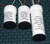
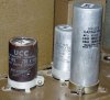
For information these are my new power supply capacitors. Rather than re-stuff the original cans I decided to use 30mm ID PVC pipe with clip in closures. The labelling is done with laser printed wet transfers and indicates the type of capacitor(s) contained within. The wiring is done with sleeved Alpha EcoWire rated at 600vdc and this will be terminated on tag strips under chassis. The sizes are similar to the originals and all will fit the existing clamps

NewCaps1.jpg Newcaps2.jpg OldCaps1.jpg

Cheers, Malcolm
 
Last edited:
Back
Top Bottom