I have been fixing A sansui 9090db for a while now,driver board ,power supply are done unit is re-capped ,keeps going green then maybe a minute or more then goes into protection.my theory is it had weak mj21194 g's hfe was 41,46,45,53,the 93's were in the 80's hfe zone,I've replaced them all,with fresh ones ,have not powered it up yet,but feel those weak ones are the issue,as I did have other techs service it while I was very sick,and it returned working ok,but felt something was off,then one night it went into protection, now I am feeling much better and decided to dive in!well I found on f-2624 board they had reversed c09 & c10,it did have balance issue ,and the night it went out it was same symptom could turn it off and back on it would go green then ,go back into protection, so even after addressing driver board all transistors except for c984's,it did same thing so I purchased a known working board and it tested good,same thing???so that has led me to the outputs and the low hfe ?could that be issue?I've restored quite a few in my day but this unit has been my nemesis for years now,I do have a few tricks up my sleeve if it does not pan out and my theory goes kaput! But oh wise ones your input would be greatly appreciated, I have c984's on hand and a new Omron relay,but running out options .


You are using an out of date browser. It may not display this or other websites correctly.
You should upgrade or use an alternative browser.
You should upgrade or use an alternative browser.
Weak outputs transistors Sansui 9090db
Register to hide this ad

h(FE) is quite sufficient. It almost always differs significantly between PNP and NPN transistors. This is normal. First find the cause of it going in protect. Does it actually have DC on the output? Sometimes a protect circuit misbehaves. It does not go into protect because of h(FE).
You must not replace semiconductors willy-nilly but go about it systematically. Oh, and use a DBT.
You must not replace semiconductors willy-nilly but go about it systematically. Oh, and use a DBT.
Was just following path of c09, c10 because they were swollen and they were down to 28 uf,meaning possibilities of stressing every thing in path,including outputs which when put in were definitely not in forty hfe zone,so not much choice and trust me no nilly - willing around here I research my brains out until I make a move,guess it could be protection circuit,board
How it worked for almost a year with the backward caps is beyond me ,but it did stressing all things in its path as they slowly piddled out to 28uf ,during that year it sounded good,but with balance had to be at 10 o'clock to even out speakers, so systematically working out from those caps.
And the real pisser of it all before my heart attacks, I had it restored to the point of it powered up and biasing dead on,but had a fuzzy side. was to sick so turned it over to some tech guys who said between them they had a hundred years experience between them!and were like real proud of themselves and very dismissive, they were the best ,just ask em,and they would tell you all about how awesome they were,so why they worked the
Poor driver board to death and scoffed at my pinning of the Dolby board,and re-did it with rivets,and it does seem to function fine ,but it did before,then put in c09,and c10 in backwards, I even got them gigs at local record store that I did some repairs for before I got sick,I did not want to leave the record store owner hi and dry ,so I vouched for them and that has since backfired on me,they(the tech guys) have shut down their business.so that is my issue it was just a fuzzy side for goodness sake,did text them picture of board with reversed caps and the back of the over worked and extremely repaired traces and pads.so now its my problem ,those caps the 100uf 25v are coupled to the bias transistors and outputs, 180 ohm resistors and 150ohm resistors,then down to the power supply transistors, and for the tech guys you would chew your arm off to get out of the conversation off how awesome they are and they know more than most people,have gone radio silent.
Poor driver board to death and scoffed at my pinning of the Dolby board,and re-did it with rivets,and it does seem to function fine ,but it did before,then put in c09,and c10 in backwards, I even got them gigs at local record store that I did some repairs for before I got sick,I did not want to leave the record store owner hi and dry ,so I vouched for them and that has since backfired on me,they(the tech guys) have shut down their business.so that is my issue it was just a fuzzy side for goodness sake,did text them picture of board with reversed caps and the back of the over worked and extremely repaired traces and pads.so now its my problem ,those caps the 100uf 25v are coupled to the bias transistors and outputs, 180 ohm resistors and 150ohm resistors,then down to the power supply transistors, and for the tech guys you would chew your arm off to get out of the conversation off how awesome they are and they know more than most people,have gone radio silent.
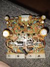


I just tested the hfe of the 2 used but good MJ21194G's I have in stock - and the hfe's? 41 and 43 - so I don't think your output transistors can be stressed in a way that reduces their hfe.Oh and my theory also is that because of reversed caps it stressed the 94 g's down to that low hfe of 41,and should power on up now and stay green!just keep chickening out of pushing that ole power button.
As regards C09 & C10, they are for filtering the noise off the zener diodes they are connected across, installed reversed they would have really messed up the DC offset setting. They may have pulled enough current to mess up some of the nearby resistors, (like R05, R07 and their opposite numbers in the other channel), so I advise you to check them carefully, and of course install new C09 & C10.
Last edited:

The hfe of a transistor can vary a great deal depending on the current level that the hfe is being measured at. Those small component testers are measuring the hfe at a rather low current for output transistors. Heck, much of the current gain of output transistors is swamped out by the emitter resistors.

What I have found is what others have said, the 40s are normal on those mj21194, i usually see 40-50s. Something Dr. Audio mentioned once was for any given output; look at the datasheet online as it will list the Min normal hfe. If you do your test and you get below the Min hfe then yes the outputs need to be replaced as they are starting to get weak.

All those fuse resistors need to be replaced. I see a couple of solder blobs on the back, not sure if that's an issue but it could be. The fuse resistors should be replaced with new metal film 1% or 5% 1/2W resistors. Don't use two resistors in parallel, just get the right values. Replace all those fuse resistors except the larger 3.9k don't need replacing normally. TR01-04 should be replaced if they are still original.
Those pictures are what it was like,when I opened it up,two resistors were not me ,but thank you,that's kinda why I ranted away last night.so if I addressed,those issues and still have issue, and it is not what I thought (41 hfe theory) they were all matched when I put them in,some where in the 70's -80hfe. So they took a hit.so now my thought goes to protection board and relay,and the state of soldering on driver board, any now taking the advice and getting a dim bulb for next round.ding ding
Thank you very muchI just tested the hfe of the 2 used but good MJ21194G's I have in stock - and the hfe's? 41 and 43 - so I don't think your output transistors can be stressed in a way that reduces their hfe.
As regards C09 & C10, they are for filtering the noise off the zener diodes they are connected across, installed reversed they would have really messed up the DC offset setting. They may have pulled enough current to mess up some of the nearby resistors, (like R05, R07 and their opposite numbers in the other channel), so I advise you to check them carefully, and of course install new C09 & C10.
As the real and true,of this is I am trying to fix it,so if things go side ways with my health again and I don't make it ,my wife would have no problem selling it,all my other receivers are restored,(marantz 2275,sansui 8080,sae 2400l,ect,ect) this one is the bane of my existence. So that is my mission statement "get er' done ,before I'm done". But I am doing well for now .thank you all for your input look forward to hearing more.
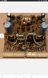

I have this board which tested good,and was stated came out of working unit,few thing s to change like fuse resistors,and another thing on first board that steamed me was they replaced the transistors with nte transistors,in their defense I think my two tech buddies bit off more than they could handle,because this model has humbled many seasoned techs.and yes they were friends for years, just disappointed in them and some of there choices,

Jefft91
Active Member
Here's what I think you said you're seeing happen:
1) Amp starts up okay
2) After it runs for a while it goes into protection
3) Powering down, it can be powered up into a working state - is this right away, or do you let it cool down.
I'm wondering if you're having issues with the bias not tracking properly with temperature. As your system heats up, the thermal tracking device should reduce the bias to avoid thermal runaway. If that happens, maybe your protect circuit kicks in. I'm not that familiar with this model's protect circuit, so apologies if I'm off-track here.
1) Amp starts up okay
2) After it runs for a while it goes into protection
3) Powering down, it can be powered up into a working state - is this right away, or do you let it cool down.
I'm wondering if you're having issues with the bias not tracking properly with temperature. As your system heats up, the thermal tracking device should reduce the bias to avoid thermal runaway. If that happens, maybe your protect circuit kicks in. I'm not that familiar with this model's protect circuit, so apologies if I'm off-track here.
No off and then back on goes green ,then into protect,so far have gone all the way back to relay,going to test capacitors on protection board,replaced relay ,old one original ,arcing on two contacts.nothing awful but bad enough. So you were right on track,because I believe that I addressed the thermal possibility, and some of the posts are directing me to protection board,and I am running out of boards,most of them have been re-capped . except FM/am boards,and above symptom is how it went out one night.but it was stressed by backward capacitors on driver board,