• The move to the new server is done. There are some software and database maintenance updates in process. This has us passing the hat around to help out. We appreciate any donations. Seriously, even a dollar helps. The payment page may be found here - https://www.audiokarma.org/support.html

What type of wire?

AZBiker

New Member
Hello,

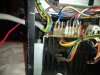
I'm working on a 2330b. I found that one of the wires that connects to the P700 board through a connector, broke at the connector. It's a two-conductor wire that goes to the Power Amp In RCA jacks on the back. It appears to be simple 2-conductor wire but it could also be shielded; it's difficult to tell because there's a piece of heat shrink where they stripped the wire.

The exposed part of the wire is solid because they used wire-wrap to make the connection. My question is, does this need to be a twisted pair or a shielded single conductor due to it being in low-level audio path? It's the same type of wire that goes to many of the low-level inputs on the back of the unit. Thanks in advance!
 
Register to hide this ad
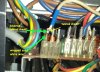
It would be the black and white wires on the left. Due to the heat-shrink, I can't tell if it's shielded since all I see are two solid conductors. Which would make me wonder, why did they heat-shrink it after they stripped it back? Let me know if you need a better pic..
 

Attachments

  • IMG_20230327_065650936.jpg
    IMG_20230327_065650936.jpg
    113.9 KB · Views: 57
Could be the heat shrink is to keep the shield braid from shorting something nearby if it came into contact. You could check the other end of the cable. Shielded cable usually has the shield connected to ground at one end.
 
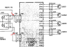
This schematic from the SM shows that it is a shielded wire. This could be braid or foil with a drain wire. You can check the other end at the Main-In RCA jack to verify. My guess is the heat shrink is covering a solder joint to connect the braided shield to the solid wire to wrap to the post. If it is not shielded, it could be twisted pair with one side to ground. If it is 2-conductor solid wire, the heat shrink could just be to cover the cut outer cover.
upload_2023-4-17_13-52-29.png
 
You may be able to strip it back a little and resolder. Or add a short extension and heatshrink that to insulate it. If you have to redo the whole thing I'd try RG-174 coax. It's a bit fatter though.
 
This schematic from the SM shows that it is a shielded wire. This could be braid or foil with a drain wire. You can check the other end at the Main-In RCA jack to verify. My guess is the heat shrink is covering a solder joint to connect the braided shield to the solid wire to wrap to the post. If it is not shielded, it could be twisted pair with one side to ground. If it is 2-conductor solid wire, the heat shrink could just be to cover the cut outer cover.
View attachment 2862612

Thank you. That's what I was thinking; a solid wire was soldered to the shield thus the heat shrink tubing. Thanks for verifying! And good eye in the schematic.
 
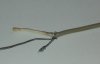
Okay, I decided to bisect this wire. It appears there is a solid, bare wire, a shield and an insulated solid wire. Makes sense since it's low-level audio. The black insulation that was on the bare wire was slid on by either the factory or the last person to work on it. The wire gauge is 24 AWG. Just an FYI in case you run into this.

For me, this is the big problem with wire-wrap; you need 1-1/2" of bare wire in order to re-wrap it if it breaks. I cringe when I see wires soldered to wire-wrap posts. It's just not a clean look. I'll hunt down some of this wire and do it right. Thanks for all your replies!

Now all I have to do is locate some. It appears to be rare.
 

Attachments

  • IMG_20230418_071243263.jpg
    IMG_20230418_071243263.jpg
    33.6 KB · Views: 23
Last edited:
Okay, I decided to bisect this wire. It appears there is a solid, bare wire, a shield and an insulated solid wire. Makes sense since it's low-level audio. The black insulation that was on the bare wire was slid on by either the factory or the last person to work on it. The wire gauge is 24 AWG. Just an FYI in case you run into this.

For me, this is the big problem with wire-wrap; you need 1-1/2" of bare wire in order to re-wrap it if it breaks. I cringe when I see wires soldered to wire-wrap posts. It's just not a clean look. I'll hunt down some of this wire and do it right. Thanks for all your replies!

Now all I have to do is locate some. It appears to be rare.
You may not like the look but it's a solid, reliable corrosion free connection. I like the reliability of doing so myself. Of course just my opinion and you must be satisfied first and foremost!
 
When I started working (long ago), we used wire wrapped digital boards on Navy ships. Of course, the wire wrap pins were gold, but this provided a good electrical connection since each wind of the wire actually contacted the post a 4 points... so with 10 winds = 40 electrical contact points. These survived even the salt laden sea environment and shipboard shock and vibration with reliable connections. The advantage of using wire wrap (vs PCB) was that you could make changes to the circuit design by unwrapping and re-wrapping wires. As a side note, if you are careful you can sometimes unwrap and re-wrap connections by using an unwrapping tool then straightening the wire and re-wrap.
 
IIRC, I was taught that the wire wrap created an oxygen free connection, as opposed to soldering.
And in vintage work, I'll unsolder the pin rather than unwrap (I don't actually own a wrapping tool, I should get one) since it's unlikely I'll ever be able to re-create that excellent wrap connection.
 
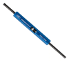
FYI - Many, many years ago the technicians at work used to wrap boards with 210 (16-pin) digital ICs (3,000+ connections). To connect a wire to multiple IC pins you would use 2-level wire wrap to 'daisy-chain' the connections. The wire wrap tool looked like a small drill with a bit that held the wire and spun it around the wire wrap pin when the trigger was pulled. The unwrapping tool was essentially a small tube that slid over the wire wrap post with a small hook at the end. This would catch the wire and loosen it when turned CCW. I used to have a manual wire wrap tool that actually did an excellent job of making clean, tight wraps. What the manual tool didn't do was to wrap the required insulated part of the wire around the base of the pin a couple of turns.
upload_2023-4-20_10-14-47.png

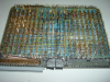
The boards looked sort of like this from the back (photo courtesy djekerson.com). Making corrections to a board was easier and quicker than a layout change to a multilayer PCB.
upload_2023-4-20_10-17-49.png

You NEVER put more than two wraps on a single pin so you had to plan out the signal route (top & bottom wires) so it worked out right. A 'wire list program' took the schematic and generated a table of wire wrap from-to wires for the tech to follow. Note: you can see the couple of turns of insulated wire from this photo. Photo courtesy of bigmessowires.com.
upload_2023-4-20_10-24-18.png
 
Last edited:
Looks like sheer torture to me! Forty years in the biz and never had to do that. I was lucky!!

By the way, yes wire wrap makes oxygen free contact points but so does solder. If not, explain it to me to cure my ignorance (quite likely). :)
 
For me, this is the big problem with wire-wrap; you need 1-1/2" of bare wire in order to re-wrap it if it breaks. I cringe when I see wires soldered to wire-wrap posts. It's just not a clean look. I'll hunt down some of this wire and do it right. Thanks for all your replies!
What is a PITA. I understand the OCD gets damn serious with vintage gear, buying a box for a c-note and paperwork for 25bucks for a sheet or two and insisting on wire wrap fits this level. Nothing wrong with it but I don't know if much stuff is worth that.

I worked on a Pioneer where the Previous owner did the recap and instead of wrestling the board out of its parking spot which wasn't too difficult, he cut every wire wrap leaving a small chunk of insulation for connection. What a worthless way to do that work. Moving the board while connected and maybe one or two of the wraps might break, soldered back in place, all good, move on.
 
One more thing from the past. We used to use these crimp-on type gold connectors to crimp onto the wire, cover it and the wire with heat shrink tubing, then slide it over the wire wrap post. This was useful for jumpers and test leads because it was removable.
upload_2023-4-20_21-51-13.png
 
IIRC, I was taught that the wire wrap created an oxygen free connection, as opposed to soldering.
And in vintage work, I'll unsolder the pin rather than unwrap (I don't actually own a wrapping tool, I should get one) since it's unlikely I'll ever be able to re-create that excellent wrap connection.
I decided to bite the bullet and get a wrap/unwrap tool. Very simple and effective. But, I've heard of other folks unsoldering the pin and that works, too.
 
Back
Top Bottom