• The move to the new server is done. There are some software and database maintenance updates in process. This has us passing the hat around to help out. We appreciate any donations. Seriously, even a dollar helps. The payment page may be found here - https://www.audiokarma.org/support.html

What's the difference between a Butterworth and Linkwitz-Reilly?

So, I’m trying to figure this out...

Assuming I leave the midrange crossover alone (it’s a first order bandpass using a 3.9uF cap and .56mH inductor in series), how do I know what type the tweeter is using and how to modify it?

What I mean is, as I understand it, I can’t change the cap value and not the inductor value, correct?

Original cap is 2.2uF, and inductor is .4mH. Experimenting with online calculators, I can’t determine what type of second order this is (be it Butterworth, L-W, etc.). None seem to fall with the values already installed. Do I start from scratch calculating a tweeter crossover, and leave the mid alone? If so, which type do I use?

Or, can I simply swap the cap and not the inductor?

More here than I may understand, would swap the tweeter for a more direct replacement if I could find one.

Thanks,

Joe
 
I've been away for a bit and missed a lot here.

Joe, you CAN change the cap and inductor independently, but the effects on the overall response curve of the system will obviously be different. Without some measurement equipment you won't really know what is happening.

I'd suggest trying it as-is (adjusting only the resistor) to start and see how it sounds. I would also wire the new tweeter in the same polarity as the original. Then see how it sounds.

If there are obvious peaks or dips, or the tweeter is too hot (or not loud enough) you can go from there.

I have seen the same thing you have: actual component values in a crossover do not calculate out to the crossover frequencies reported by the speaker manufacturer. Most likely because they've tweaked things based on the response curves of the individual drivers, or to manage the impedance curve, or dampen peaks or dips around the crossover frequency, etc.
 
BTW my original question was intended to get at 'what's the math' and 'aren't there just two slightly different equations for calculating these schematically equivalent circuits?' Turns out the math is fairly complicated.

Butterworth Filters: https://en.wikipedia.org/wiki/Butterworth_filter

To wit:

A transfer function of a third-order low-pass Butterworth filter design shown in the figure on the right looks like this:

f8e35010e098bf3cd8a7690ec4a423c620bc420a


A third-order low-pass filter (Cauer topology). The filter becomes a Butterworth filter with cutoff frequency ωc=1 when (for example) C2=4/3 farad, R4=1 ohm, L1=3/2 henry and L3=1/2 henry.


A simple example of a Butterworth filter is the third-order low-pass design shown in the figure on the right, with C2 = 4/3 F, R4 = 1 Ω, L1 = 3/2 H, and L3 = 1/2 H.
[3] Taking the impedance of the capacitors C to be 1/(Cs) and the impedance of the inductors L to be Ls, where s = σ + jω is the complex frequency, the circuit equations yield the transfer function for this device:
a8ea11e7d7a86f537d11d1ddb3a259627224ebae

The magnitude of the frequency response (gain) G(ω) is given by
f6f233f866833e49ad93b17771dc30f34dd1986f

obtained from
28f6674b1e0673e5cded36ad6d8b5fb2c66dc80d

and the phase is given by
569fb36acf92dfd6b0ce18d48bff3652d3eb2e7e


Well, duh. Obviously! o_O

So to make a L-R you just stack all of this up double. Got that? :p
 
Thanks, Tox. Appreciate you putting everything into basic terms, and practical recommendations.

So, I tried a 3.5 ohm Mills resistor in series instead of the presumed 2 ohm magic number to keep total impedance at 10. Sounds pretty darn close to where I want to be in terms of volume, but seems to have a slight overlap with the mid (at least to the ear; upper mid seems a hair exaggerated). Will use REW if I have to to confirm, but that’s what it seems.

With a 1.8 ohm resistor, overlap seems gone, but they’re too bright for my tastes.

So, could I run the 3.5 ohm, and put say a 40 ohm resistor in parallel with the 8 ohm tweeter to effectively keep it at 6.5 ohms? Would this make a fixed l-pad then, in theory keeping the 3.5 ohm attenuation, while maintaining the ~10 ohm total load presented to the cap?

Thanks,

Joe
 
Plenty has already been said about the difference between Butterworth and Linkwitz-Riley filters. I thought I'd add this graphic I found on Wikipedia.

It compares the magnitude response of the summed Butterworth (in pink) and Linkwitz–Riley (in turquoise) crossover filters. The Butterworth crossovers have a +3dB peak at the crossover frequency, whereas the L-R filters have a flat summed output.
1024px-Linkwitz_vs_Butterworth.svg.png
 
^^ Well I'll be. Is it really that simple? Good to know. :thumbsup:
(I assume another way to deal with that peak is to wire the drivers in opposite phase?)

Back to Joe6805's question: It sounds like you are on the right track, what you're describing is a fixed L-pad. 40 ohms in parallel with 8 ohms comes to 6.67 ohms by my calculations, so yes, that should work.
 
^^ Well I'll be. Is it really that simple? Good to know. :thumbsup:
(I assume another way to deal with that peak is to wire the drivers in opposite phase?)
No. If you reversed the polarity of drivers crossed with a Butterworth crossover, the result would be a large suckout, centered at the crossover frequency, but as deep as 30 dB.
 
Last edited:
1024px-Linkwitz_vs_Butterworth.svg.png

This assumes that they are crossing over at the same frequency. But what if we set the low pass a bit lower and the high pass a bit higher so that their sum is flat/near flat in the center??? No one says that can't be done. :idea:
 
1024px-Linkwitz_vs_Butterworth.svg.png

This assumes that they are crossing over at the same frequency. But what if we set the low pass a bit lower and the high pass a bit higher so that their sum is flat/near flat in the center??? No one says that can't be done. :idea:

It can be done, but it won't result in a flat FR. You will end up 0 db at the center and two dips on either side of center. There may less total dB change than if the crossover frequencies are the same with a Butterworth, but why do it? It is easier to use a Linkwitz-Riley circuit and be assured of flat FR.

You can tell it will not work because the curves are different. If you shift the Butterworth curve over so that the HF and LF curves cross at -6 dB, the displaced curves will not coincide with the Linkwitz-Riley curves, which is what you need for a flat FR.
 
I suppose by now I should have just made a separate thread for my situation, but several have replied here.

So, as mentioned above, I considered a parallel resistor across the tweeter to make a fixed L-pad.

Would it be a better option to run a 2 ohm (1.8 ohm is what I have laying around) resistor in series to “make” the proper 10 ohm load for the cap, then run an actual L-pad to get the sensitivity right? Parts Express has 50w, 8 ohm L-pads for cheap...

Leaning that way, just wanted to make sure it was the best route.

Thanks,

Joe
 
It can be done, but it won't result in a flat FR. You will end up 0 db at the center and two dips on either side of center. There may less total dB change than if the crossover frequencies are the same with a Butterworth, but why do it? It is easier to use a Linkwitz-Riley circuit and be assured of flat FR.

You can tell it will not work because the curves are different. If you shift the Butterworth curve over so that the HF and LF curves cross at -6 dB, the displaced curves will not coincide with the Linkwitz-Riley curves, which is what you need for a flat FR.

One can get a flat response using a Butterworth first order crossover.
it requires a sloped front time aligned zero plain delay design.
Exact driver placement on the baffle is critical to achieve a flat response.
image_34009.gif
 
One can get a flat response using a Butterworth first order crossover.
it requires a sloped front time aligned zero plain delay design.
Exact driver placement on the baffle is critical to achieve a flat response.
View attachment 1496276

Sure, a speaker can have a reasonably flat FR using a first order crossover. But that requires that the drivers and the enclosure parameters to be matched to the electrical crossover. The Burhoe Module, e.g., EPI M100, is one example of a speaker system where the acoustic response, when combined with an electrical crossover, produces a good result.
EPI 100 ad w-freq resp chart.jpg

But that is not what is being discussed when just considering the effects of the crossover by itself as in most of the posts above.

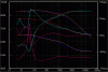
PS: I suggest including a legend identifying the individual traces in your chart. Without identification of each trace, the chart is undecipherable.
 
Sure, a speaker can have a reasonably flat FR using a first order crossover. But that requires that the drivers and the enclosure parameters to be matched to the electrical crossover. The Burhoe Module, e.g., EPI M100, is one example of a speaker system where the acoustic response, when combined with an electrical crossover, produces a good result.
View attachment 1496303

But that is not what is being discussed when just considering the effects of the crossover by itself as in most of the posts above.

PS: I suggest including a legend identifying the individual traces in your chart. Without identification of each trace, the chart is undecipherable.

I don't have the graph of the mid bass driver anymore.
Enclosed is the response of the Hiquphon tweeters.

My whole point is that a flat response can be achieved with a Butterworth crossover.'
The sims is actually a quasi 2nd order series crossover.

I have never liked the sound of 12db per octave Linkwitz Riley crossovers since the tweeters are out of phase.
Curve-OWII.gif
 
I wish others posting on this thread would read some of the links post by knowledgeable people like Pete B post #17 and myself.

There is more to a flat response with a crossover.
Phase and amplitude are just as important.
browse.cfm
 
I wish others posting on this thread would read some of the links post by knowledgeable people like Pete B post #17 and myself.

There is more to a flat response with a crossover.
Phase and amplitude are just as important.
browse.cfm

It is important to get the vocabulary correct.

Someone talking about a flat response is typically referring to the frequency response (FR), which is generally plotted as amplitude over frequency. Another consideration separate from FR is phase, which is typically plotted as phase angle over frequency. Yet another consideration is impedance, which is typically plotted as impedance over frequency. Often, traces for each of these plots are overlaid on one chart using the same frequency axis. Together, these charts provide information about speaker performance.

Also, remember the AK motto: All Audio, No Attitude.
 
The speaker has so much to do with the crossover that they really need to be considered together to get optimum results. The reality is that the LP and HP may need over be spaced or overlap to get best results because the speaker will have its own anomolies that will affect the slope.

I've put a lot of effort into the crossovers I use with the Ethyl Mermans (JBL 2241H 18"/ JBL 2251J 10"/ Heil AMT) and the crossover is based on both the speaker anomolies and room acoustics and is very unconventional in it treatment of the midrange. The 6.8 mfd (previously 9.2 mfd) was supposed to connect to ground..., and did in one of the two units. But in the other I accidently connected it to the wrong side of the 47 mfd ( as shown) and thought I was grounding it. When comparing the two speakers, one definitely sounded better and I had to find out why. I discovered my error and this arrangement was the better sounding of the two, and rather than "correct" it, I changed the other.

The results and detail are truely outstanding and I haven't wanted to listen to the "veiled" L300s since. For example when listening to a reverberation decay on the L300s you hear when it ends..., but if you then change to the Ethyl Mermans, it is still hanging there for some time.

This assumes the use of the wedgie in the Heil. The UHF switch provides a ~5 dB boost ~14,500 Hz to add sizzle/air but does not let the signal get low enough to reinforce any peaks at lower frequencies.

ScreenHunter_205_May_01_16_51.jpg
 
Back
Top Bottom