• The move to the new server is done. There are some software and database maintenance updates in process. This has us passing the hat around to help out. We appreciate any donations. Seriously, even a dollar helps. The payment page may be found here - https://www.audiokarma.org/support.html

What's the weirdest factory mistake you've found?

It's a good thing that you kept those security guards warm while they huddled around that heater all day. Probably prevented a terrorist attack.
Yeah, it kept them on their post. They had been going into their office to keep warm.
 
Last edited:
On a McIntosh MX110, the L/R record output jacks were reversed from the factory. On a MAC1500 receiver, the L/R outputs from the headphone jack were also reversed.
 
Was the polarity silk screened backwards on the PCB, and the ensembles pit them in according to what they saw printed on them? Thats just really an odd one for sure.
To me it looks like it was a misunderstanding of the "dot" on the silkscreen. Perhaps somebody marked the "+" and it was used as "-" or vice versa.
 
Very interesting. Here's some comments from people selling their Effectrons, "They're not the warmest sounding...it's is a quirky, entertaining device with lots of character...also capable of some pretty wild and weird sounds". Could the backwards caps been the cause for their "sales pitch"? :dunno:
Yes, the unit came with all kind of "whine" noises, many exploded low voltage capacitors. After replacing them, the problem came back. Tracing the circuit due to lack of schematic revealed the origin of the problem. After reversing the capacitors, the unit preformed silently and perfectly as it should.
 
No weird problems, just the usual solderless solder joints. They can work for years, so they pass test. Eventually they vibrate loose or oxidize and a problem shows up. I've seen it in speakers, amplifiers and even expensive test equipment like meters and oscilloscopes.

There are two "electronics 101" design mistakes I sometimes see. First is tube equipment where they put voltage dropping resistors between the lugs of a filter capacitor. The resistors get hot and the heat gets conducted down the cap terminals, shortening the life. They really need to be on a nearby terminal strip. A similar problem is a filter cap right next to a power tube. The second design mistake is bad power supply layout where a ground gets connected to a charging trace for a filter cap, putting voltage pulses into the amplifier circuits.
 
I had a new SUV, where the front and back windshield washer fluid levers worked on the wrong windows.

I never had them fix it. So confusing, when I switch cars. ;)
 
There are two "electronics 101" design mistakes I sometimes see. First is tube equipment where they put voltage dropping resistors between the lugs of a filter capacitor. The resistors get hot and the heat gets conducted down the cap terminals, shortening the life. They really need to be on a nearby terminal strip. A similar problem is a filter cap right next to a power tube. The second design mistake is bad power supply layout where a ground gets connected to a charging trace for a filter cap, putting voltage pulses into the amplifier circuits.
Good info, thanks for sharing!
 
Bought a McIntosh MA8950 two months ago. After about 2hr it would shut-down due to thermal overload. Power transformer was very hot. They gave me a new one which has been fine. Turns out the 1st one was wired for 100vac. Someone did not pay attention when building and/or shipping, as the box was marked 120vac.
 
You're just assuming that the soldering was done by the factory. Maybe someone just had better soldering skills than the common tinkerer.
They would have to be VERY good at soldering. I've been doing this for a decade and I can resolder wires onto a pot plenty neatly, but to do it without leaving some evidence is a tall order.
I can't imagine why someone would have swapped these two controls after the fact, but it is easy to picture someone getting them mixed up on the assembly line.

Maybe I'm wrong, but this being a factory error seems most plausible.
 
An error on the Service Manual of the McIntosh MC712 "System Control Center" preamplifier... :thumbsdown:

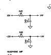
Look at the polarity of C44 : the schematic is wrong and so is the layout ! :eek:

1703441248414.png 1703441295689.png

Fortunately, C44 was installed correctly on the PCB... :)

Nonetheless, I have been well advised to check and note all polarities of the caps before performing their replacement ! :naughty:

1703441577018.png

Oh yes, certainly... :biggrin:;)

T
 
Have a ‘48 RCA tv - one connection in the horizontal osc section was never soldered at the factory. Must have acted up all the years it existed. Soldered it as part of the recap - thing worked beautifully.

Another RCA solid state amp, the power amp’s soldering and the component installation suggested it was a Friday afternoon amplifier.
 
Ampeg VT-22. The capacitor that drives the reverb tank was only soldered on one end. The other end floated freely in the PCB hole and never made contact with the trace.

Believe it or not, this top of the line, 100W 2x12 amplifier was purchased new in 1972, and was only ever used in the owners basement rec-room for quietly learning/practicing jazz guitar. He never used reverb, so he really didn't care. When I purchased it, it was mint :oops:
 
technics sa-5550: channels wired in reverse for the headphones. i read this was common.

concept 3.5: a damaged trace for the bass pot. it sure appeared to be a factory defect with all the flux and crap in it. it took me months to find it.
 
This wasn't weird, rather ignorance on the part of NAD. When I got my 2200 amp there was a lack of bass. Turns out they used the wrong caps to decouple the low voltage regulators. They were 1uF and should have been at least 470uF.
 
The usual bad or missing solder that others have found, nothing too special.

Closest thing to a "mistake" is probably more of a highly questionable engineering choice. The stock main filter caps in a Phase Linear 700 are 100 volts. The supply in mine ran at 108 volts.

There is another case of what I'd call a questionable design choice in an old CB I have. Uniden made the boards for a bunch of brands including some Realistic (Radio Shack) models. RS for some reason specified different transistors in this specific unit, instead of the EBC pinout these were CBE. They were essentially identical other than the pinout. Every transistor in the thing is backwards vs the silkscreen on the board. If you find that same board in a Cobra, Uniden, President, etc the transistors match the print on the board.
 
logitech_squeezbox-0005.jpg

Logitech Squeezebox with the connections to the display board missing soldering.
 
Back
Top Bottom