• The move to the new server is done. There are some software and database maintenance updates in process. This has us passing the hat around to help out. We appreciate any donations. Seriously, even a dollar helps. The payment page may be found here - https://www.audiokarma.org/support.html

Winter project: Pilot AA-920 conversion to power amp

This winter I wanted to convert a rusty Pilot AA-920 to mono power amp.
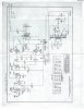
I could use a schematic if someone has one. I might change the circuit as well because I will have extra sockets and power.
Here is my progress so far:

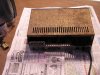
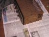
Rusty!
P1010019.JPG
p1010021.JPG
P1010020.JPG
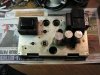
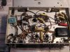
Looks a lot better!
P1010019 (2).JPG
P1010025.JPG
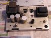
The second amp is Reversed(mirrored)!
P1010028.JPG
 
Last edited:
Register to hide this ad
OK, do you mean changing it so it's no longer a "Integrated Amp" ?
I have the same Pilot AA-920 Integrated Mono Amp however, it's missing the LARGE Transformer. I (hopefully) will one day have a qualified Tech replace the Transformer and update this unit as mine is in wonderful (physical) condition. I have no idea why the Transformer is missing as I bought it "as is". Good luck with your Winter project. Oooh, any information you might have/come across regarding that large Transformer would be greatly appreciated if you could post information. Thanks.

SixCats!
 
Yes, I'm removing the preamp parts.
I can measure the voltages if it would help.
One interesting thing, the 2 amps are almost mirrored, I'm adding the pic to the first post for easier viewing
 
Last edited:
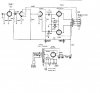
Here is the stripped down schematic,as it sits.
The amp could use a little more gain.
One amp has a 240 ohm cathode resistor,the other 330
pilot 920 conversion.jpg
 
Last edited:
Can you use a 12AX7 to replace teh 12AU7, for teh driver and PI ? Or use teh 12AU7 for teh PI and input tube, and something like a 6AV6 for the driver?

Regards,
John
 
That's quite close to the AA-410a which is the UL version of the pentode AA-410 amp. I'll dig up my (messy LOL) marked up schematic and post it. And you're not the only one to have two different cathode resistors ... my brass plated amp has the 250 ohm as per the schematic and the aluminum chassis console version is 330 ohm. I left them, but other then that both amps have identical circuits before and after the rebuild.

Here is the stripped down schematic,as it sits.
The amp could use a little more gain.
One amp has a 240 ohm cathode resistor,the other 330
pilot920conversion_zps72aa6768.jpg
 
Last edited:
Amps sound very nice using JAN 6C4's, Amperex 12au7's, and Philips JAN 6L6WGB's.
 

Attachments

  • Pilot AA-410A-01.jpg
    Pilot AA-410A-01.jpg
    61.5 KB · Views: 71
  • Pilot AA-410a Schematic - Modded.jpg
    Pilot AA-410a Schematic - Modded.jpg
    90 KB · Views: 78
That's a pretty simple design, if I can find an OPT that is similar, I think I'll put it on the list of things to try... Thanks for posting it...

Regards,
John
 
You could bypass the cathode resistor with a cap on the 6C4 to get a little more gain out of it. That would reduce the local feedback at that stage, though you risk adding some non-flat response from that. Maybe a small film cap would give enough oomph without messing up the frequency response.
 
I tried a 12Ax7,it didn't seem to help with the gain,I thought it would?, I have to try the other suggestions.

It sounds great as is, but I need more gain.
How much more gain would it have with another 12AX7 stage? (6C4 vs 12AX7)

There is also the option of fixed bias,as there is a 20v tap on the transformer for DC filaments

If someone has a chassis like the first one,i may be interested (large hole on the side,not in the center)
 
Last edited:
I tried replacing a 6SJ7 driver, that I substituted half a 6SL7(12AX7) for to increase gain, but it started to distort, so I used half a 6SN7(12AU7), and it still wasn't enough gain,,, ended up using both sections 6SN7, and the gain increased some, but I still would like more,,,, no distortion tho,,,
Hope you sort it out, as I'm out of ideas,,, looking fwd to see what you come up with...

Regards,
John
 
Yes, that would be the 'as built' schematics. Just remembered that they also have fuses now.
 
Well... the amp is supposed to have a sensitivity of 1.2v for 15w output.
I am going to try a 6ab4 in place of the 6c4,ala Fairchild 260, it should almost be a drop in replacement,possibly i will bring the feedback to the input tube s well.we'll see...
 
Substituting the 6AB4 seems to get it pretty close, It sounds much better.
I think one of the 12AX7 sockets could be used to install a 12AT7 if a 6AB4 is not handy
I still can't drive it into clipping with my Blackberry

I also changed the coupling caps to .1 from .o47.
I am surprised the feedback loop doesn't have any caps in it, I have to bring out the o-scope and sig gen to finish it
pilot 920 conversion.jpg
 
Last edited:
Looks good, I'd like to find an octal close to 6AB4/12AT7... which cathode resistor did you end up using...
You're way ahead of schedule, if this is a winter project!!

Regards,
John
 
On the 6L6's? 330 for now, I may try the 240 later as long as the tubes don't overheat, all other resistors are as marked in the schematic.

I am going to do a little more research to see if I should change any of the other values.

I still have to figure out what to do to the chassis, to cover the extra holes.
The second chassis has a larger hole in the center of the chassis which kind of mucks things up a bit. If they were like the first one, I could make an angle plate across the front and part way over the top. I have a friend who owns a trophy shop, I would have a brass plate made for that.
 
Thanks, I'm following your schem, and making the changes along the way,,,
If you are using the covers for the amps, the chassis holes won't matter,,, if they are going to be open, I'd just put a plate under the unused holes, or if they really bother me, I'll just bend a fresh chassis, but then you have to cut/punch/drill every hole... But, you could match the other chassis that way,,, Its pretty easy to do, with a little metal brake...

Regards,
John
 
Back
Top Bottom