• The move to the new server is done. There are some software and database maintenance updates in process. This has us passing the hat around to help out. We appreciate any donations. Seriously, even a dollar helps. The payment page may be found here - https://www.audiokarma.org/support.html

Winter project: Pilot AA-920 conversion to power amp

Thanks for the feedback!
It sometimes seems as though no one is interested.
I guess it's good to go for now, the caps don't heat up, the amp gets warm over 3 hours, but not hot(no problem keeping my hands on anything except the 6CA7's(I would leave skin behind, but no red plating).
I will still have to tune the fb loop(currently stock) likely tomorrow.
Awaiting replacements for the mismatched parts.
after the feedback is done I will post the complete schematic
 
Last edited:
OK, do you mean changing it so it's no longer a "Integrated Amp" ?
I have the same Pilot AA-920 Integrated Mono Amp however, it's missing the LARGE Transformer. I (hopefully) will one day have a qualified Tech replace the Transformer and update this unit as mine is in wonderful (physical) condition. I have no idea why the Transformer is missing as I bought it "as is". Good luck with your Winter project. Oooh, any information you might have/come across regarding that large Transformer would be greatly appreciated if you could post information. Thanks.

SixCats!

The transformer is a bit of an oddball, it has the following voltages,20v center tapped, 5v, 6.3v center tapped.760v center tapped at 120v input
 
Don't know what FB resistors your schem calls for, I usually put a pot in temporarily, makes it pretty easy to dial in... Glad its not getting too hot, my output tubes are close to the PT, needed to shield em...
 
Currently the resistor is 6.8K(stock),but no caps in the circuit, after I connect it to the scope, who knows?.
Some measurements: 33v across the 330 ohm cathode resistor for the pair of tubes. about 100 ma B+ current after the rectifier. B+ is 440v
 
The transformer is a bit of an oddball, it has the following voltages,20v center tapped, 5v, 6.3v center tapped.760v center tapped at 120v input

Being made for a receiver the 20 volt winding was for the preamp tubes , rectify the 20 volts to DC add a cap and you have 24 volt for your two phono preamp tubes and maybe even bias for the output tube .
 
Well.... it gets a little warm after 3 hours, I can barely keep my hand on the power transformer. I also need to raise the cathode resistor to ~340 ohms, as the 6N3c's are barely red plating. I still have to do the FB loop.
If anyone sees anything else that is not optimum please let me know.

One strange thing, as the tubes just begin to conduct there is a crackle once from the speaker. It may be there is too much voltage in the preamp / driver tubes as they begin to conduct. it peaks at 490v just as they start to conduct.
Hindsight being what it is, I would have made a larger chassis, instead of keeping the original footprint.
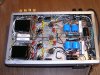
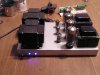
P1010033.JPG P1010034.JPG P1010035.JPG P1010037.JPG

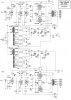
Here is the current schematic and progress of the amp
stereo920-R4.jpg


The pilot LEDs are powered from the cathode voltage, so they come on as the amp warms up
 
Last edited:
Looks good, you're well ahead of schedule for a winter project! I like teh ground buss and teh aluminum resistor heat sink looks familiar... Are they 6L6s,,,How does it sound?
 
http://www.hammondmfg.com/jpeg2/158SA_B.jpg
http://www.mouser.com/Search/Refine.aspx?Keyword=1H,+240mA+choke+553-C24X

158SA you might fit a couple of these on your chassis , they are less than $8.50 each at mouser .

it would get your voltage down a bit

I would think about it ,but I don't think they will fit, the chassis height is 1.25" and a bit crowded.

The amp sounds good,no hum.It will get a bottom cover soon
I'm currently switching between vintage EI EL-34'S AND 6n3c'S

Yes, the heat sink came in handy, the rest of the inverter was unrepairable
 
Last edited:
This was a practice amp, I have several others to build.My skills are pretty rusty at this point. I made several mistakes on this amp.
 
Looks pretty good to me...should sound pretty good also,,, I never heard EL34s...
There's always hindsight, I don't think I left any of my builds alone... keep reading, and learning more, then trying it out...
 
When I started collecting 35 years ago, I liked power, and gear was plentiful,
so, I passed on anything less than 6L6's and 7591's, another hindsight mistake.
 
Live and learn... 35 years ago, I was building/playing with cars as a hobby,,, they got too hard to work on in the last few years,,, I needed a new hobby, renewed the "stereo interest", from many years ago,,, Building amps is easier on the old bones than cars!!!
Really glad I found you guys...
 
The amp is basically finished, needs a bottom cover feet and some touchup
It puts 15.6v into 8 ohms(onset of clipping) with an input of .9v there is 10db of negative feedback(stock)
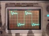
first pic is the stock circuit o=scope trace 10 K squarewaves
The second is after feedback adjustment
stock10k.JPG pilot 10Kfinal.JPG

The finished schematic
stereo920-R5.jpg
 
Last edited:
I used the original value, I just added 330pf cap across it,and added a 12pf cap across the plate resistor of the 12AT7, I just realized I might have made a mistake both in practice and the schematic,I should have added it the the 12AU7.
I have to go back and change it,At 20k the square wave had a little dip in the center,and using the 12AT7 was too sensitive(I couldn't use my R/C box because of stray capacitance in the wiring)
 
Last edited:
Some thing to try is to put a 100 ohm to 220 ohm resistor in series with the 330 pf cap and look at the wave form , that may get rid of the ring and give better rise time to the square wave .
 
I tried it,it seemed better that way, I have to put it where it is in the schematic,instead of the 12AT7, and readjust.
 
Last edited:
Back
Top Bottom