• The move to the new server is done. There are some software and database maintenance updates in process. This has us passing the hat around to help out. We appreciate any donations. Seriously, even a dollar helps. The payment page may be found here - https://www.audiokarma.org/support.html

"Working" receiver does not put out any audio

Smellycorpse

New Member
I have recently come into the possession of a Kyocera R-861 receiver. It was sold as "working". It looks like a very lovely machine. The wood-grain paneling could use a little love, but I will fill in the broken-up edges with wood putty and carefully paint it to match the veneer. Won't be perfect, but it won't catch the eye like the bare particle board underneath does.

But I have a bigger problem. The receiver puts out zero sound. The receiver turns on, changes sources, can scan for radio stations, etc. But I do not hear a hum or a buzz, even if I turn up the output all the way, regardless of whether I have speakers or headphones plugged in. No tubes, just mosfets.

In the past, I've been lucky enough to be able to visually identify faulty components and replace them that way. I have not used a multimeter since high school and do not remember how to use it but I found a nice one at an estate sale a few weeks ago that I have yet to use, so this will be new territory for me. This is a very wonderful receiver, so it is very important that I give it the care and attention that it deserves, as I have almost completed my collection of Kyocera gear. (I even have the impossible to find RS-103).

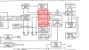
I found a service manual online that is too large for me to upload here. (https://www.hifiengine.com/manual_library/kyocera/r-861.shtml). Probing with a multimeter feels intimidating when there are so many components on the board, and because I don't want to break the multimeter by mistake, but I'm sure it presents a good learning opportunity. I'd feel rather foolish if I spent an hour probing around some FM radio circuitry simply because I couldn't read the diagram and differentiate it from the rest. With the aforementioned symptoms, where do I even start looking, and what do I test for?

I've tried using different headphones, plugged the speaker wires into both Speaker A and Speaker B ports, depressed the speaker A/B buttons on/off, turned mute off and on, etc. The usual troubleshooting items that may be obvious.
 

Attachments

  • Kyocera r861.jpg
    Kyocera r861.jpg
    93.4 KB · Views: 41
Register to hide this ad
We all started out knowing pretty close to nothing so if you want to learn, there are lots of people here who will help. There are some really good YouTube channels out there and you can learn a lot from watching them troubleshoot problems. The basic process applies to most pieces of equipment. You can also learn a lot about how to read a schematic, and it looks like you're going to need to know how to do that. xraytonyb has a good YouTube channel you might want to check out and there are other good ones too.

First thing - safety. Most solid state stuff is fairly low voltage but there's still line voltage in there. It's never a bad idea to keep one hand behind your back and use only one hand to probe around. You can get a probe with a clip to hold the negative probe on the chassis so you don't have to hold it there. That's where you'll want it for a lot of the measurements you'll do.

If your meter has probes with long metal ends on them, be very careful poking around. If you touch two of the wrong things with the same probe at the same time, you can short something and do some damage. Probes with a very short exposed metal contact point are less dangerous. Also, google "mini-grabber leads." They're very handy when you want to connect the meter without holding the probe with your hand.

All that said, I don't know anything about your receiver specifically. In general, I'd probably start by checking the power supply to see if it's putting out all the right voltages and that they're getting to the places they're supposed to go. The schematic will probably have a voltage marked at a bunch of points in the various circuits and if you see something way off, that's a clue. With absolutely no sound from any input, I'd probably check the output transistors next. You can do at least a basic check of transistor health with your meter if it has a diode check function. Google and YouTube are your friends there too.
 
Last edited:
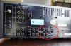
Looking at photos on the web your unit appears to have a "Pre Out Main In" switch of some sort on the back. It looks like it is typically locked in place by plastic and a screw to prevent accidental movement. Is that in place? Like you I try to start by eliminating the simple especially on a complex unit like this. Sharp looking unit BTW.
 
Looking at photos on the web your unit appears to have a "Pre Out Main In" switch of some sort on the back. It looks like it is typically locked in place by plastic and a screw to prevent accidental movement. Is that in place? Like you I try to start by eliminating the simple especially on a complex unit like this. Sharp looking unit BTW.
If it has that, you can use it to figure out if the pre-amp is working and if the main amp is working. If one of them isn't, at least it narrows down where the problem is.
 
Looking at photos on the web your unit appears to have a "Pre Out Main In" switch of some sort on the back. It looks like it is typically locked in place by plastic and a screw to prevent accidental movement. Is that in place? Like you I try to start by eliminating the simple especially on a complex unit like this. Sharp looking unit BTW.
i've "repaired" several units just by flipping that switch, cleaning that switch or by installing missing jumpers.
 
Any chance its something as simple as the tape monitor button being on?
I've turned the tape monitor on and off, but that hasn't made an impact, unfortunately.


Looking at photos on the web your unit appears to have a "Pre Out Main In" switch of some sort on the back. It looks like it is typically locked in place by plastic and a screw to prevent accidental movement. Is that in place? Like you I try to start by eliminating the simple especially on a complex unit like this. Sharp looking unit BTW.

There is a piece of plastic w/ a screw that is locking the switch into the connect position. I figure this is how it's supposed to be configured, would that be right? I can try unscrewing it and toggling the switch back and forth to see if that changes/loosens anything or maybe clean the connection a little bit. It does look very sharp. I've collected a matching tape deck, CD player, and Remote Control center, and I imagine everything should be looking really sharp once I have it in place. I am looking forward to that.


If it has that, you can use it to figure out if the pre-amp is working and if the main amp is working. If one of them isn't, at least it narrows down where the problem is.

Would I accomplish this by putting a multimeter in resistance mode and checking for continuity? (I only have an analog multimeter with no dedicated continuity mode) If so, I imagine that I would probably put the positive terminal into the main-in input, and then the negative terminal somewhere like the headphone output for the corresponding Left/Right channel? And then this might tell me if the connection between the audio output and the amplifier (I don't know if the receiver being unplugged would change that, however) Or is my thinking/thought process off the mark.
 
Would I accomplish this by putting a multimeter in resistance mode and checking for continuity? (I only have an analog multimeter with no dedicated continuity mode) If so, I imagine that I would probably put the positive terminal into the main-in input, and then the negative terminal somewhere like the headphone output for the corresponding Left/Right channel? And then this might tell me if the connection between the audio output and the amplifier (I don't know if the receiver being unplugged would change that, however) Or is my thinking/thought process off the mark.

You can hook up a known working power amplifier to the pre-out, and a known working preamplifier to the main-in
 
You really need to find somebody to sit down with and get the basics of measurement. Could you put your location in your profile?
 
First questions (since I've not seen one of these in person): Are the selection and tape monitor switches mechanical or electronic (do they latch down when pressed --mechanical -- or just "click" without locking -- logic switches). It matters, as mechanical switches oxidize and you can lose the signal to poor connection. Logic switched could be failed logic or a back switching chip.

Do the selector LEDs work correctly?

Does this unit have a remote control?

If it has an "always on" circuit for a remote control, likely it's not working, so nothing else does either including the selector logic so you have no signal to the amp at all. The tuner and the LEDs are usually driven by a separate 15 or 18V circuit.

Also, just discovered there is a "remote/standard" switch for the volume, make sure it's in the "std" position or you won't have a volume control unless you use the remote.
 
Last edited:
Would I accomplish this by putting a multimeter in resistance mode and checking for continuity? (I only have an analog multimeter with no dedicated continuity mode) If so, I imagine that I would probably put the positive terminal into the main-in input, and then the negative terminal somewhere like the headphone output for the corresponding Left/Right channel? And then this might tell me if the connection between the audio output and the amplifier (I don't know if the receiver being unplugged would change that, however) Or is my thinking/thought process off the mark.

No. Don't do that. it's probably too difficult to explain in detail here all the things you need to know. Where are you located? Maybe there's someone nearby who could help.
 
Last edited:
What meter do you have? Do you have a soldering iron and solder? I suspect the unit may be in protection mode.
 
All that said, I don't know anything about your receiver specifically. In general, I'd probably start by checking the power supply to see if it's putting out all the right voltages and that they're getting to the places they're supposed to go. The schematic will probably have a voltage marked at a bunch of points in the various circuits and if you see something way off, that's a clue. With absolutely no sound from any input, I'd probably check the output transistors next. You can do at least a basic check of transistor health with your meter if it has a diode check function. Google and YouTube are your friends there too.

I'll do some searching around and try and learn how I can test these components safely. Continuity checks I am pretty sure I can do. Testing voltages i think may be a little more challenging, but who knows. I've a lot to learn.

I think I have done some good work to narrow things down. With sources plugged into the inputs, and cables between the pre-out and an external amplifier provided to me by a friend to borrow, I was able to hear the various sources through the external amp when the switch was set to "separate".

With sources plugged into the amp and then plugged a pre-amp into the main-in and couldn't get any feedback from the receiver. I assume then that this means that this problem would require looking at the power amp. I imagine I likely do not have to look at the Speaker A/B selector, peak indicators are likely irrelevant. I am also assuming speaker relay protectors might also not relevant. Glad to rule all of the pre-amp out of the equation though.
 

Attachments

  • 861 amp.png
    861 amp.png
    193.6 KB · Views: 7
I'll do some searching around and try and learn how I can test these components safely. Continuity checks I am pretty sure I can do. Testing voltages i think may be a little more challenging, but who knows. I've a lot to learn.

I think I have done some good work to narrow things down. With sources plugged into the inputs, and cables between the pre-out and an external amplifier provided to me by a friend to borrow, I was able to hear the various sources through the external amp when the switch was set to "separate".

With sources plugged into the amp and then plugged a pre-amp into the main-in and couldn't get any feedback from the receiver. I assume then that this means that this problem would require looking at the power amp. I imagine I likely do not have to look at the Speaker A/B selector, peak indicators are likely irrelevant. I am also assuming speaker relay protectors might also not relevant. Glad to rule all of the pre-amp out of the equation though.
That's good info. I think you've ruled out a bit too much though. Good to know the pre-amp is working but main amp, speaker selector switch, and protection circuit/relay are all still possibilities.
 
Either it's in protection, the speaker switches are bad (no connection between amp and speakers) or the "separate" switch is bad.

You can check the switch with a DMM, should have zero ohms through it set to "normal" and infinite set to "separate".

I don't know if this amp has a speaker protection relay or grounds the input, either system is used, but if something is wrong the amp will shut off the speakers or main amp to prevent smoking the speakers.

Check the postion of that "remote/std" switch under the volume slider.
 
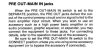
..your unit appears to have a "Pre Out Main In" switch of some sort on the back. It looks like it is typically locked in place by plastic and a screw to prevent accidental movement. Is that in place?

..There is a piece of plastic w/ a screw that is locking the switch into the connect position. I figure this is how it's supposed to be configured, would that be right?

Yes, you want it in the "Connect" Position"

Screen Shot 2023-06-11 at 6.56.21 PM.png


Screen Shot 2023-06-11 at 6.46.30 PM.png


I had a Sansui AU-717 that had a similar "Connect/Separate" switch, it wouldn't hurt to just double check that the "Connect" position is nice and secure.
 
This receiver has a speaker protection relay. Do you hear a click about 5 seconds after you turn it on? If not, the output transistors (Mosfets) are probably blown on one channel.
 
You really need to find somebody to sit down with and get the basics of measurement. Could you put your location in your profile?
No. Don't do that. it's probably too difficult to explain in detail here all the things you need to know. Where are you located? Maybe there's someone nearby who could help.


Profile has been updated. I'm from Utah, here.

What meter do you have? Do you have a soldering iron and solder? I suspect the unit may be in protection mode.
The meter I have is an old Radioshack Micronta Multitester Cat. No. 22-203A. I do have a soldering iron, wick, and some solder, however.
 
First questions (since I've not seen one of these in person): Are the selection and tape monitor switches mechanical or electronic (do they latch down when pressed --mechanical -- or just "click" without locking -- logic switches). It matters, as mechanical switches oxidize and you can lose the signal to poor connection. Logic switched could be failed logic or a back switching chip.

Do the selector LEDs work correctly?

Does this unit have a remote control?

If it has an "always on" circuit for a remote control, likely it's not working, so nothing else does either including the selector logic so you have no signal to the amp at all. The tuner and the LEDs are usually driven by a separate 15 or 18V circuit.

Also, just discovered there is a "remote/standard" switch for the volume, make sure it's in the "std" position or you won't have a volume control unless you use the remote.


The unit does not come with a remote, but I have the remote control accessory that can be used to control it. The selector LEDs works just fine however, and I can toggle between all the sources pretty quickly with the remote control. All the sources seem to work when the pre-amp is connected to the external amplifier.

The receiver is intended to plug into the "remote control center" which is a separate unit with switched outlets that sends commands via rca cable to the unit. The unit itself has no sensor and turns on due to the switched outlets it is plugged into. Most of the buttons are soft-touch buttons except for the power button and a few of the filter buttons.
 
This receiver has a speaker protection relay. Do you hear a click about 5 seconds after you turn it on? If not, the output transistors (Mosfets) are probably blown on one channel.
You are right - I do not hear a click. I will look at the output transistors when I have a chance. The peak indicators go off when I have the radio or another device plugged in, so I now know the audio is making it as far as the indicators in the power amp.
 
Back
Top Bottom