• The move to the new server is done. There are some software and database maintenance updates in process. This has us passing the hat around to help out. We appreciate any donations. Seriously, even a dollar helps. The payment page may be found here - https://www.audiokarma.org/support.html

Wurlitzer 660. I got the Wurlitzer bug.

Stand By ! I can't seem to downsize the pix. PM sent and three pix of Wurlitzer manual pages sent to you...
 
Last edited:
So I got one of them up and running today using the much better schematic that @tubeactive sent me. I really wanted to mess with this biasing design. Using the website that @gadget73 sent me I wanted to try to use diodes in place of the resistor that lifts the center tap off the ground. It worked and produced -100vdc but when I got the tubes in it was drawing too much does the diodes and they got so hot it melted the solder holding them together.

I then put a 1500ohm 25 watt resistor in place and got about -110vdc. After all the chokes and resistors it ended up being about -80v at the interstage center tap. I put a 4700ohm resistor and 10k pot in and that gave me plenty of adjustment for bias. Set to 50v for a 280v plate voltage. IMG_7614.jpegIMG_7616.jpeg

I think I like this version better than the 771. Using different resistor configurations you can lower the plate voltages and increase bias voltages. The 771 uses almost 100v over the maximum recommended plate voltage for a 45 tube. I got this down to 280-260 plate voltage which should extend the life of the tubes. The only issue with that is it affects the preamp heater voltages go down with b+ voltages since the are dc voltage.
 
Its going to pull a lot of current, a small zener, resistor, and trimmer won't handle the load. I'd suggest trying it stock first to get an idea of currents and such before changing anything.

keep in mind the back bias setup handles the full current load of the entire amp. Thats 3 45 tubes plus whatever the front end pulls. Probably pushing 100ma. That makes for a lot of power dissipation.
 
The trimmer taps off the negative line and only goes to the grids of the outputs so there’s almost no amperage going through it. It is drawing about 75ma through the center tap resistor or about 9 watts so those 5 watt zeners never stood a chance.
 
So when deciding the maximum C1 capacitance does that include all 3 of these first capacitors, the 2 that go to the center tap and the one that goes to ground? The 5z3 has a maximum c1 of 40uf. This put its at 45. The fact that the chokes are on the center tap is also throwing me off. IMG_7618.jpeg
 
first cap the rectifier sees is C7. C8 has the L2 choke between it and the negative side so you get the impedance of that to knock down peak currents. C9 has L2 plus anything else between that point and ground. Electrically its the same as if it was on the positive side so far as the rectifier cares.

With a 5Z3 you can probably 20uf easily without it having problems. I wouldn't go too nuts here though.
 
I got one up and running. After trying different combos of resistors I got the plate and bias voltages right. I swapped the national output transformer that I put in the 771 in this one and it’s makes all the difference. I think the output transformers on these really are the weak point in these. I listened before and after the OT change and it’s night and day. The original is very muddied. With the upgraded OT it’s bright and powerful. My point being is that I don’t see any reason to change the interstage transformer unless I come across one on the cheap.

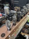
I’m amazed at the amount of power wasted through resistors in these amps but I guess it’s needed since it was using a field coil speaker. I just wish the “hammered copper” paint came out more copper and less rose gold. But I think it looks pretty good IMG_7644.jpegIMG_7647.jpegIMG_7631.jpeg
 
The other thing I noticed is the 45 driver tube uses a 75k ohm grid leak resistor which seems to be very low. I think the spec is 100k-500k. With a .1uf coupling cap gives a 21hx cutoff frequency. Maybe I’ll experiment there too IMG_7649.png
 
I decided to change the capacitors and grid leak resistors. First I changed the input resistor from 100k to 1m ohm. Then the first coupling cap from the 1b5 to the 30 from .1 to .47 and the 30 grid leak from 250k to 300k. Then the 30 to 45 driver I kept the .047uf but raised the grid leak from 75k to 330k which should give me about 10hz cutoff. I also replaced the electrolytic bypass cap with a 40uf film cap I had laying around. I had yo raise the plate resistance on the 1b5 and 30 tubes because the plate voltage were a little above max.

That all really woke this amp up. Super clear and plenty of bass. These amps and 45 tubes really are something special.
IMG_7657.jpeg
 
Keep in mind when this was made. In the 30s you were dealing with 78 rpm records as the primary source. Turntables had a lot of rumble back then and 78's didn't really have much in the way for high frequency response. It made sense to limit the bandwidth of the amp so it wasn't trying to reproduce noise.
 
Designed as an in-console, jukebox system.
The Spkr Field coils also help HV filtering, besides using them as B+ bleeders. The Magnavox 15" which came with these is quite wide bandwidth, plus it's "fast" sounding.
Bandwidth of the intrstg is fine. Opts are only a bit limiting.

When I run mine, I use a single 30, adjusting voltage dividers accordingly.
The 1B5 and first 30 are part of the phono preamp, not needed for amp duty.

Itza must to try 45 Globes and 30 globes, if possible...

Keep up the good work @Carbsandcaps
 
I did noticed there’s definitely distortion at higher volume levels like too much gain. I was gonna see how it sounds without the 1b5 but the 1b5 has diodes in it I was assuming that was for the dc heaters. I would love to try gloves if they weren’t so astronomically expensive
 
The diodes are tied to the heater because its the cathode. its just shorting them out so they don't cause issues. Its a triode / double diode used as a first AF, AVC and detector tube in radios. Same as a 6AV5 or a number of other tubes like it. The diodes are good for very little current.
 
Interesting. I guess I’ll experiment with bypassing the 1b5 next. Maybe I’ll leave it in for looks. I don’t like empty spots.
 
Back
Top Bottom