• The move to the new server is done. There are some software and database maintenance updates in process. This has us passing the hat around to help out. We appreciate any donations. Seriously, even a dollar helps. The payment page may be found here - https://www.audiokarma.org/support.html

X-202-B: mod to extend output tube life?

artarchives

New Member
Hi,

I'm new here.

I've got an X-202-B that seems to blast thru the output tubes way too quickly. Right now, I have a new set in channel A with only ~50 hrs on them and I'm starting to get loud squeals intermittently. The unit has been to several techs and had a lot of components replaced, but no "mods" as far as I know. I can solder and follow directions, so I'm taking matters into my own hands.

I scrolled thru some threads and there's a staggering amount of knowledge here. I've gathered that frequent output tube burnout is something of a common issue due to design. Is there a basic mod that addresses this?

Thanks,
Will
 
Register to hide this ad
If you're not familiar with a dim bulb tester(DBT) ,google it. I'm not a tech but I would replace all the original electrolytic and film caps and later the trim pots (careful here, may need a dim bulb tester) . Then check voltages against SM and ask best way to biased the amp. Welcome to AK
 
Thanks for the warm welcome.

The last tech charged me $100 to bias the currently used tubes, so I hope it was done correctly!

I will look into the Dim Bulb Test. As for electrolytics, I bet those were done during an extensive overhaul I had yrs ago. Sorry for lack of certainty here. I'll try to post gut photos later, if that's helpful.
 
Strange squeals and crackling can be signs of dirty output tube sockets. You might want to clean and tighten them (DeOxit). If the control grids are making poor contact, this can affect the bias voltage and cause the tubes to run too hot. May well not be the problem, but easy to do and good practice from time to time with our old gear.
 
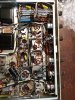
Attached are some photos of the underside guts, in case they are of use. I checked on some old service emails and the amp has had two pretty extensive overhauls. One of the electrolytic caps appears to have been replaced, but not the other for some reason.

I think I'm past the Dim Bulb Test since I've had the amp running and, besides the occasional squeals, seems to not be having catastrophic failure.

As for tube socket dirtiness, that's definitely worth looking into, thanks. But I'd think my problems would be more consistent and unaffected by the tube's age, or am I wrong? I've had this amp for a long time and it's always been the same old song: when there are new tubes it works great for a month or so, then the pops/squeals start creeping in on one channel. Then I put it in the closet for a while til I feel like buying another set of tubes and having it biased.

As I said before, I had a tech bias the amp recently with a new set of tubes. But perhaps he didn't do it right. Could someone kindly point me to directions on how to bias the amp?

Thanks again to all.
 

Attachments

  • fisher guts 1.jpg
    fisher guts 1.jpg
    186.5 KB · Views: 48
  • fisher guts 2.jpg
    fisher guts 2.jpg
    173.4 KB · Views: 45
I have one of these amplifiers and it has 2 adjustments for setting the bias current of the 4 output tubes. What I did was to install a 1 ohm 3W wirewound resistor in series with each output tube (7591) cathode and its return connection so that I could monitor individual tube bias currents using a hand held DC millivolt meter. Order 1% ones for best results. If you can measure that low a resistance, then pick any 4 that are alike and note the common resistance reading. The X202-B has two adjustment pots to set bias, and I twiddle those until I get 35mA (35mVdc) across all the 4 tubes' resistors. The settings of the two controls interact, so you go through an iterative process of adjusting one and then the other a few times until you settle onto the right current for all the 4 tubes.
 
Thanks, egellings.

Pardon my ignorance, but can't I just check the biasing by taking voltage measurements from the grid (pin 6?) to chassis ground? Alas, I don't know the magic number for the proper voltage there - I'm a novice at deciphering schematics.
 
Checking pin six will only tell you the negative bias voltage for the tube, which is useful but not sufficient (it ought to be around what the schematic shows, but the schematic target is approximate: -19V. It should be in the ballpark, but this is not meant to be exact). Depending on the condition of each tube, the actual tube current draw, which IS the most important thing, will vary, so you need to determine the actual current draw (cathode current) of each tube. Here's how:

If your unit is stock, there is a 10 ohm 5W resistor between the cathodes (the number 5 pins) and chassis ground for each pair of 7591s. The actual resistors are located between the output transformers underneath. To determine the tube cathode current draw, measure at the hot end (non-ground) of the resistor and divide that voltage by 10 to determine mA for each PAIR of tubes. Divide that by 2 and you have the average current draw for each tube in the pair. As I recall, the resistors are wired the same as the tubes when viewed from underneath--that is, the left resistor is for the left hand 7591 pair, and the right for the right pair (double check the wiring to verify).

Before setting the bias levels, warm up the amp with no signal applied and set the DC balance for each pair. The simplest way is to to set your DMM for a low voltage range (1-V unless it's auto-range) and hook one lead to the plate pin 3 of one tube in a pair and one lead to it's companion plate pin 3 and adjust the DC balance control for that pair for a difference of zero volts (as close as you can get). BE CAREFUL--you're measuring at the tube plates, which are operating over 400VDC here and you don't want to get that across your body! Carefully use clip leads to connect so you're not trying to juggle two probes and the bias pot adjustment at the same time.

Then, set the bias level for the pair using the bias level control for each pair, again with no signal applied to the amp. A good target for 7591 cathode current per tube in this amp would be 35mA per tube, or 70 mA per pair. To set this, you would measure across the 10 ohm resistor for the pair and adjust the bias level for 700 mV for the pair. Divide that by 10 and you have the current for the pair via Ohm's Law: 0.700V / 10 Ohms = 0.07A, or 70 mA. Divided by 2, that's 35mA for each tube.

The bias settings are interactive, so you may need to go back and forth a couple times to get the tubes set where you want them, as one adjustment can affect the other and you are 'tuning it in' with successive measurements.

A 35mA cathode current draw less about 3mA for screen current draw would give an idle plate dissipation of 0.032A x 440V plate voltage = 14.1W, or about 74% of the maximum spec anode (plate) dissipation rating for the 7591 of 19W.

Again, take care when measuring and setting the bias in this way to avoid a painful and possibly fatal shock!

Dave

 
You can also add 2 more resistors that Dave was talking about (separating each pair to individuals). Keeps the averaging down and allows you to see if you have a load hog (one drawing a lot and the other low draw).
 
I just set up to adjust the DC balance, per Dave's instructions, with speakers connected and the amp is now making all manner of heinous racket: squeals, drilling sounds, pops... Will I damage anything by moving forward without speakers connected so I don't have to listen to that mess? Or maybe I've got bigger problems now than just bias? The amp didn't sound like this when I had it hooked up a month ago, odd.
 
Larry, I actually did do that for the one I restored. I also re-purposed the remote control socket (as Dave G did) to serve as the test points for setting bias, running leads from the output tube cathodes to the remote socket. Built a little jig to plug into it and allow the DMM to be hooked up to measure the cathode voltages.

One thing I couldn't understand was why Fisher used 5 watt, 10 ohm resistors for the cathodes of the tube pairs. Way more wattage than needed. I put 10 ohm 1/2W resistors between each 7591 cathode and ground for current measurement, typical of today's practice.
 
atarchives,
Don't run it with the speakers unhooked or some kind of proper load (like a non-inductive resistor) across the speaker outputs. When troubleshooting this kind of stuff, a good set of power resistors across the outputs save the noise of having to listen to it. Plus, you don't want to damage your speakers.

I still would work on the tube sockets as a start, but you may have bigger problems in hand, such as problems with the negative feedback circuit (oscillation), etc. I take it the problems are on both channels?
 
Dave,

Yes, both channels. Initial startup produced some intermittent pops, then after a minute or so of warmup the wall of noise began.

Thanks for the power resistor tip. Would this work, soldered to RCA's? https://www.digikey.com/en/products/detail/ohmite/AG10NF8R0E/13914843

I will get into those tube sockets. I'm pulling up a zillion different kinds of Deoxit when I search Digikey - which is the one I want? And while I'm at it, anyone care to point me to a good brush for getting in there?
 
...One thing I couldn't understand was why Fisher used 5 watt, 10 ohm resistors for the cathodes of the tube pairs. Way more wattage than needed. I put 10 ohm 1/2W resistors between each 7591 cathode and ground for current measurement, typical of today's practice.

DaveG put up a wonderful tutorial on a X-202-B restoration. In it there was an adjustment to the bias scheme of he original design. Included was the removal of the 5w biasing resistors and the installation of individual 10ohm resistors at 1/4w. Dave451 is right, 5w is overkill for the application. Another X-202-B In The House!!

I've had my X-202-B running since the fall. Nary a squeak of being upset. Post 2 DaveG zeroed right into where I'd put my money: bias out of whack. If you're going to put in an order, get a ton of metal film 1% resistors 1/4w but no more than 1/2w. The smaller the device, the more likely it'll let go in an overcurrent situation which is a secondary but very important safety adjustment to the original design.
 
I use Gas Torch Welding tip cleaners (Lincoln) for initial cleaning with DeOxit DNS-5 spray, (spray some in the cap and use a toothbrush on tube pins.). Later if it gets noisy, I'll go raid the Dental section at Walgreens and get some "interdental" brushes (used to clean out Braces). You'll also need a small jewelers screwdriver to tighten up the tube socket leaves. Loose socket leaves can cause squeals, clicks, pops, etc. as the pins expand from tube heating, and the surface of the pin moves in the socket. The socket leaves won't expand from heating as fast as the pins (tube heating as source), so there is some rubbing, and contact resistance.
 
Those resistors will work fine as long as you don't run full power through them (being 10W). The key is they are non-inductive. Wire them across the 8 ohm/common speaker terminals taking care not to short the speaker terminals.

I looked at the schematic again, and the "speaker off" switch position puts the power amp across 24 ohm 7W resistors (for headphone listening), so you ought to be OK just switching the speaker switch to 'off' as long as you're not putting a full power signal through.

What you don't want to do is just unhook the speakers and run the amp with the speaker switch still "on".
 
Back
Top Bottom