• The move to the new server is done. There are some software and database maintenance updates in process. This has us passing the hat around to help out. We appreciate any donations. Seriously, even a dollar helps. The payment page may be found here - https://www.audiokarma.org/support.html

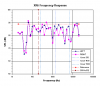
XR6 Frequency Response

To much data won't let you see the forrest to mix metaphors. So....

Is the "blue trace" for the speaker that has the bass noise issue?

1/3 octave pink noise is still used for testing because it more closely duplicates music's sound character. Using pure tones at 1 meter will help find your woofer noise issue, will help find cabinet rattles etc., but it will not help see the speaker's character.

I can't help but wonder if the deep null at the top of the woofers response is related to the air leak/woofer noise?
 
Too much data won't let you see the forest to mix metaphors. So.... Is the "blue trace" for the speaker that has the bass noise issue?

1/3 octave pink noise is still used for testing because it more closely duplicates music's sound character. Using pure tones at 1 meter will help find your woofer noise issue, will help find cabinet rattles etc., but it will not help see the speaker's character.

I can't help but wonder if the deep null at the top of the woofers response is related to the air leak/woofer noise?


The speaker that's buzzing is the VIOLET trace or SN 1635. Remember they've been switched side-to-side. I've revised the spreadsheet by digitizing the Cal curve in the SLM Users Manual. Data points at 90, 900 and 9000 have been removed for smoothness. Also.. the sample at 200 Hz has been altered for smoothness. Now there are TWO fudged samples (see RED font.) The imbalance is reduced to 2.12 dB

Revised Data Sheet attached.​

The technician types will like the TWO Calibration curves (see tab #2 of spreadsheet.) One is from a online magazine article, and the other is from the Rad Shack User's Manual. Yep Chris, I have your OCTAVE test chart in spreadsheet form now and will be going that route next, however it won't be as fast and easy to 'dial in' those odd frequencies on the Sig Gen.


-Greg
 

Attachments

Last edited:
The null at 200Hz being in both speakers but greater in 1635 rules out that being caused by the air leak/noise in the woofer. What is causing this null? These peaks?

Theory 1) There was a marketing strategy by a English audio company promoted in TAS that stated you could not audition their speakers in dealers showrooms if multiple speakers would be on display in the dealers audition rooms. The other speakers would act as some sort of traps that would absorb certain frequecies, alter their speakers sound, and diminish their wonderfullness. As a dealer it was a pain but sometimes there is a kernal of truth in these marketing ploys: Are these nulls caused by you testing these speakers side by side?

Theory 2) What in the room is there to interact with the speaker? The wavelength of 150,160,200,300,400 Hz are 7.5,7.0,5.6,3.75,2.8 ft. respectively. The 8 in. lower mid driver is 18 to 24 inches off the floor and it's bandwidth is from 250 to 1.4k Hz with I believe 12 dB per octave slopes. It has been a long time since I studied wave physics and with the test frequecies not at 1/3 octaves it is harder to see multiples, but are we not seeing nice even multiples here which would show floor coupling?

Theory 3) There is a problem in the crossover between the lower mid and the mid dome pulling down the dome from 1.4k to 7k therefore exaggerating the peaks. It would almost have to be in R4 and D3 but in both speakers? It is interesting to compare the XR16 crossover to the XR6.

Enough to think about and test.
 
The null at 200 Hz being in both speakers but greater in 1635 rules out that being caused by the air leak/noise in the woofer. What is causing this null? These peaks?

Theory 1) There was a marketing strategy by a English audio company promoted in TAS that stated you could not audition their speakers in dealers showrooms if multiple speakers would be on display in the dealers audition rooms. The other speakers would act as some sort of traps that would absorb certain frequencies, alter their speakers sound, and diminish their wonderfulness. As a dealer it was a pain but sometimes there is a kernel of truth in these marketing ploys: Are these nulls caused by you testing these speakers side by side?

Theory 2) What in the room is there to interact with the speaker? The wavelength of 150,160,200,300,400 Hz are 7.5,7.0,5.6,3.75,2.8 ft. respectively. The 8 in. lower mid driver is 18 to 24 inches off the floor and it's bandwidth is from 250 to 1.4k Hz with I believe 12 dB per octave slopes. It has been a long time since I studied wave physics and with the test frequencies not at 1/3 octaves it is harder to see multiples, but are we not seeing nice even multiples here which would show floor coupling?

Theory 3) There is a problem in the crossover between the lower mid and the mid dome pulling down the dome from 1.4k to 7k therefore exaggerating the peaks. It would almost have to be in R4 and D3 but in both speakers? It is interesting to compare the XR16 crossover to the XR6.

Enough to think about and test.

The buzzing woofer has been fixed!!

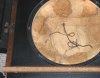
It turns out that the wires to the bass driver were quite long and the area behind the woofer is almost completely filled with packing. See imprint of basket in absorber material below. Seems the excess wire was laying beside the driver frame. I bundled both HOT and NEG wires (mostly the black one) with cable ties and stuck then behind the magnet. The black wire was longer and had a different jacket material, shiny like it was rated for higher temps. Here is a photo of the driver wires with 'wraps' applied to eliminate buzzing.
XR6_servicing_19.jpg
Cable ties bundling excess wire behind magnet to eliminate buzzing below 85 Hz. Note basket imprint in absorber material.


After removing the 12" bass driver of S/N 1635 twice, it would appear the 33 year old gasket is almost shot in the photo above. It's about to break at any of the screw holes, and doubtful it will be usable again should the woofer be dismounted.

It's convenient to work on these cabinets laying on the carpet with the doors opened against the sectional sofa. You'll see a feed cable on the floor for live-tests at each step of the operation.
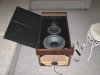
XR6_servicing_24.jpg
XR6 cabinet on its back with open door supported by sofa. Speaker cable attached at bottom for "live" CW tests.


L vs R Imbalance

The McIntosh AA2 third-octave frequency table was used this time, but the test was stopped after noticing the same 2-1/2 dB imbalance between the L vs R channels. It was time to check the voltage at the far-end of the speaker cables with a digital RMS voltmeter. Here are the results when set to 3 dB below the 2 watt `tic´ on the 2205 WATTS scale, and when set to the -3 dB `tic´ with scale to DECIBELS -20 dB.

Code:
WATTS scale:
 Freq         LEFT          RIGHT
120 Hz       2.542 V       1.845 V
400 Hz       2.539 V       1.843 V
1000 Hz      2.450 V       1.777 v

DECIBELS scale:
 Freq         LEFT          RIGHT
100 Hz       2.137 V       2.110 V
1000 Hz      2.073 V       2.048 V

So there was an imbalance in the 2205 WATTS scale. The numbers that fall out are -2.78 dB of imbalance. That would explain it!! Will be using the DECIBELS scale with meter set to -20 dB range and dial in GAIN to the -3 dB `tic´ mark.


Frequency Response

The test was halted due to imbalance in LEFT vs RIGHT but one can still observe the low response of the UM domes. The latest chart is seen below with 2.78 dB added to the RIGHT channel data points. The vertical spec lines are C33 EQ center frequencies.
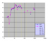
Frequency_Response_octave.png
Partial response of XR6s with 2.78 dB added to RIGHT channel due to lower input voltage.


Upper Mid driver

Both Roger and Ryan have mentioned refitting the XR series upper mid domes with a newer circular horn/dome driver. I think the model for that was MDM-55 and would require an adapter plate with similar mounting holes.


-Greg

 
Last edited:
I believe I saw somewhere a mod for the ML series that used a Morel mid dome and tweeter allong with extensive crossover mods. I find interesting the phase inversion in the XR-16 crossover vs. the XR-6.

I don't remember you recalibrating your meters after your recap, did you?

What happens to the boost at 120/150 and 300/400 when you move back 12 or 15 feet? If those peaks come down (as they should because of floor bounce) the mid wont look so low.
 
I believe I saw somewhere a mod for the ML series that used a Morel mid dome and tweeter along with extensive crossover mods. I find interesting the phase inversion in the XR-16 crossover vs. the XR-6.

I don't remember you recalibrating your meters after your recap, did you?

What happens to the boost at 120/150 and 300/400 when you move back 12 or 15 feet? If those peaks come down (as they should because of floor bounce) the mid wont look so low.

The mod is also for the XR5 as Roger pointed out..

"The Morel driver can replace the 036-035 dome if it's no longer working or is distorted. The cabinet opening will need to be changed a little to accommodate. With a slight crossover modification, it will restore the original sound and be much more reliable."​

First let's change the Mic position and do some additional response tests. The speakers and video panel are basically in an 11' x 12' alcove in the north east corner. The XR6s could also be moved out into the center of the room more.

What do you mean by the phase inversion in the XR16
?

Yeah.. I adjusted the Cal pots for 200 Watts and suggested characterizing watts full scale, but someone scoffed at the idea. Remember the "Load Plate" that could only take full power for about 10 seconds, with five minutes of forced air cooling in between?

Those peaks at at 120/150 and 300/400 Hz are likely due to the room, as is the dip at 30 Hz. You can hear distinct peaks and nulls just walking around the room while radiating a test tone. I've noted at 2000 and 4000 Hz that approaching the SLM causes a +/- 3 to 5 dB swing in the meter needle, and the center of that swing needs to be interpreted visually.

Could the UM domes really be down 7 or 8 dB? It looks like they are low over the entire 1400 - 7000 Hz range. I'm not ready to ask the Service Manager at McIntosh about it yet. Did you see this when you were AA2'ing?


-Greg
 
Last edited:
In the XR16 all drivers are wired out of phase with the woofer. I do not know why for sure. It is the only one with drivers out of phase.

If 1/4 of a wavelength from a boundry provides a cut or valley in response 1/2 of a wavelenth from a boundry should provide a boost. Trying to sort thru your data I see a boost at 120,150,300,and 400. What in the room boundry close to the speaker is a multiple of 9.4,7.5,3.7,and 2.8 ft? On top of that what standing waves does your room dimensions support? If a dimension is truely 12 feet I would look for issues at multiples(or factors) of 94 Hz. Six feet is 188Hz etc. etc. If the peaks in the 8 inch come down and the woofer with the boundry and mq104 eq come up the dip in the dome will not be so bad.

Your body can be a boundry at certain frequecies which affects any microphone.

I forget that not everyone has a 1500 watt load box.
 
This should be the last post on XR6 frequency response, as it seems everything is working ok and the system can be balanced with just one EQ section.

Test setup

For the latest frequency response test, the Mic was positioned 3 meters back from the speakers which were positioned within 1 inch of each other. The SLM on the Tiltall tripod was mounted 28" above the floor. Here is a view of the Mic using the sectional sofa as 'absorber' and to decouple from the person trying to read the sound meter.

XR6_response_dist.jpg
XR6 frequency response setup. Speakers are placed at ~1" separation.


The MC2205 amp GAIN controls were both set to produce 2.83 volts across the far-end speaker barrier strips at 400 Hz and not touched there-after. Results of the stepped CW test, both Left & Right channels operating separately were adjusted via spreadsheet to a 1-meter distance and plotted in the following chart.

XR6_response_3m.png
XR6 frequency response test results at 1/3 octave and 3 meters distance plotted in Excel spreadsheet.


Pink Noise and the AudioControl C-101

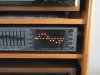
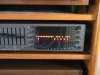
Next.. Pink Noise from the C-101 was connected to the preamp AUX input and the Mic was attached to the Tiltall tripod in place of the SLM. The trace on the C-101 LED display agrees with the spreadsheet chart as seen below.

XR6_response_AC0.jpg
Spectrum display of pink noise fed to both Left & Right XR6s simultaneously. This response agrees with the spreadsheet chart above.


C33 Equalizer controls

Examining the plots, it was decided to model (digitize) the 150 Hz EQ pot on the C33 and enter that data into the spreadsheet. Those numbers were merged with the SLM Cal column where data were all zeros. Here is the results of the 150 Hz pot set to -70%.

Corrected_XR6_response_16.png
XR6 frequency response test results with digitized C33 150 Hz EQ pot at -70% added.


For comparison, here is the C-101 LED display.

XR6_response_pot150_bass4.jpg
C33 150 Hz EQ pot set to -70% with pink noise spectrum displayed on C-101.


The scale is 4 dB/division or LED.

XR6_response_AC150.jpg
Pink Noise display with LED flickering.


Moving the speakers apart

Moving the speakers back to a separation of 56 inches, the high end comes down as would be expected with Mic no longer positioned along the tweeter centerlines.

XR6_response_150pot_sep.jpg
McIntosh system and Pink Noise XR6 frequency response with speakers separated. High end slopes due to off-tweeter axis.


Conclusion

It appears that using a SINGLE EQ section on each side of the MQ-104, specifically the WIDE 200 Hz filter cap combination will pull the overbearing high-bass/lower midrange into balance with the UMs and Tweeters.


-Greg
 
Last edited:
While your plots show case study examples of room/speaker interaction problems:
-reenforcement of 100 to 400 Hz due to floor, cut below 80 due to no near wall boundries in middle of room placement.

-comb filtering caused by 1977 driver placement and door/grille interaction.

How do they sound?

While it might fun to redesign these classic 70's speakers to modern standards you have not yet even gotten close to getting them to their potential.

I know others have noted using XR McIntosh speakers. Are you willing to be their trial horse for maximise performance with the MQ-104 these speakers were designed to be used with?
 
While your plots show case study examples of room/speaker interaction problems:

-reenforcement of 100 to 400 Hz due to floor, cut below 80 due to no near wall boundaries in middle of room placement.

-comb filtering caused by 1977 driver placement and door/grille interaction.

How do they sound? While it might fun to redesign these classic 70's speakers to modern standards you have not yet even gotten close to getting them to their potential. I know others have noted using XR McIntosh speakers. Are you willing to be their trial horse for maximize performance with the MQ-104 these speakers were designed to be used with?

They are 58" from the rear wall to the BACK of the speaker cabinet, and 71" (from rear wall) to the front of the cabinet where drivers are mounted. They sound good but cannot compare to the Thiels in terms of transient response, especially bass hits. The XR6s are somewhat muddled in comparison to the strident Thiels, however we can listen all afternoon and evening to Sonos/Rhapsody on the XR6s without fatigue, and that's why I bought them, and always wanted a pair of classic Mc speaks. They are certainly full range and warm.. not so harsh as to annoy the listener.

What can be done to the treat the doors/grills to reduce reflective interference and diffraction?

What about doing ANOTHER response test at 3 meters distance, only higher at 60 or 65" from floor?
No ones ear is going to be 28" from floor (not normally anyway.) :idea:

I'd be willing to work with others to dial these babies in even better, but no mods to the outside appearance.. ok?


-Greg
 
Last edited:
I am not sure what type of refractor would breakup the desructive cancelation caused by the door/grille. I do believe refraction to move the affect over time would be better than trying to absorb it. In the XR-16 design the polarity of the mids and tweeter were changed in reference to the woofer and the grill was a simple 3/4 inch frame.

From the picture you sent a while ago and putting the 6s in place of the Thiels, I would set the bass EQ to 2 on the RH spk(wall reenforced) and 3 for the LH. Because windows act as low pass filters you might need to raise the settings up one notch to compensate. If there are windows to the left the LH speaker you might need even more compared to the RH with its proximitry to the solid side wall.

I found that the 6s (compared to the 3,5 and 7s) responded well to a 1 inch toe in.

I would engage my customers to use the 5 band preamp eq to shape the sound. The customers input was paramount in any responsible room voicing. The use of the MQ104/107 was not some promise for room perfect response; it was an ongoing attempt to allow dealers to help a customer make their audio systems more musical and therfore more enjoyable.
 
I am not sure what type of refractor would breakup the destructive cancellation caused by the door/grille. I do believe refraction to move the affect over time would be better than trying to absorb it. I found that the 6s (compared to the 3, 5 and 7s) responded well to a 1 inch toe in.

I would engage my customers to use the 5 band preamp EQ to shape the sound. The customers input was paramount in any responsible room voicing. The use of the MQ104/107 was not some promise for room perfect response; it was an ongoing attempt to allow dealers to help a customer make their audio systems more musical and therefore more enjoyable.


Now for some extreme XR6 Response charts!!

It's useful to characterize the response of the MQ104, 200 Hz WIDE filter response from Page 6 of the Owner's Manual. These data points can be entered into a worksheet (see tab #3 of XLS file below) and used to model or predict how MEASURED data would be affected if a MQ104 parametric filter section was enabled. For you instant gratification types, the corrected response with 200 Hz filter set to -70% is seen below.

Corrected_XR6_response_16.png


To set a good example for the group, and give the guys some numbers to play with (you might want to run these tests in your room) the XR6 Response spreadsheet is attached.

Go ahead and plug some numbers into the highlighted MQ104 control cell [ -70% ].


Caps for MQ104 Wide filter section

So the plan is to order some caps (two each side) for the 200 Hz WIDE filter to insert in Section-1 of the MQ104. Then using PINK Noise with the Mic in two or three different room locations, adjust the control pot for -50 to -70% then tweak it for a couple days by ear.

That'll work for me!! :banana:


-Greg
 

Attachments

Last edited:
Are the measurements posted of the speakers in the prime listening position?

You gave the distance from the rear wall, what are the side walls?

What are the room dimensions?

Very seldom used a wide filter. Using two one above and below 200 will give you the chance to better fine tune your adjustment.
 
With all due respect, you might want to get the Room EQ Wizard fired up. It can use your RS meter's output for the mic, and will pull in the cal file values and apply them automatically.

A continuous sweep such as this takes just a few seconds...plus there is so much more it can do in terms of measurements. If you're really getting into it, it would make your life so much easier in this regard...unless perhaps you don't want it easier (and probably more accurate)?

graph_fr.jpg
 
With all due respect, you might want to get the Room EQ Wizard fired up. It can use your RS meter's output for the mic, and will pull in the cal file values and apply them automatically.

A continuous sweep such as this takes just a few seconds...plus there is so much more it can do in terms of measurements. If you're really getting into it, it would make your life so much easier in this regard...unless perhaps you don't want it easier (and probably more accurate)?

graph_fr.jpg

I agree. A sweep like this allows a much better perspective of whats happening and will take the guess work out of adjusting the filters.

I think in this case though, Gregory is trying to apply a percieved "fix" to the speakers not adjust the speakers for room interactions. He would be much better off in that case making modifactions to the crossover.

Is this graph of any particular speaker?
 
I do not wish to hijack Gregory's thread. Therefore:

If anyone wishes to explore how to use and setup their MQ101/104/107 let me know and we can open a new thread on optimising your speaker/room interface with these highly flexible parametric EQs. We can parallel the big McIntosh push on their Room Perfect with our 25 year old school technology.

To aid anyone trying to change the sound of their old XR3,5,6,or 7 I have downloaded the crossover schematics for the XR6 and XR16 for anyones input on the changes Roger made between the series. The early XR series were not a popular choice in speakers and the changes made in the later series broadened their appeal. Maybe we can collectively find ways to improve their sound by appling modern wave shaping ideas.

I have also included a XR-14 for the poster from over in speakers.
 
Last edited:
Are the measurements posted of the speakers in the prime listening position? You gave the distance from the rear wall, what are the side walls? What are the room dimensions? Very seldom used a wide filter. Using two one above and below 200 will give you the chance to better fine tune your adjustment.

The posted chart is the response of the speakers placed side-by-side with the Mic at 110" distance and 28" off the floor. For pink noise, the Mic was closer at 80" and probably 36" high. I can measure that, but didn't at the time of the test.

The distance to the walls is: 71" from driver plane to rear wall (58" from back of cabinet) and 38" from driver centerline to side walls. If the XR6s are moved to where the Thiels are now, the distances will be smaller (closer to back and side walls.) The room is oddly shaped, it's perhaps 28' deep and 20' wide. Will have to find the drawing or re-measure it.

For the narrow MQ filters, I'll have to characterize the one in the Owner's Manual and translate in frequency on the spreadsheet.


-Gregory
 
With all due respect, you might want to get the Room EQ Wizard fired up. It can use your RS meter's output for the Mic, and will pull in the cal file values and apply them automatically. A continuous sweep such as this takes just a few seconds...plus there is so much more it can do in terms of measurements. If you're really getting into it, it would make your life so much easier in this regard...unless perhaps you don't want it easier (and probably more accurate)?

That's a big 'ol plot!!

The Room EQ Wiz looks like a very good way to 'acquire' a snapshot from many different positions, and fast. It was useful to go through the exercise the old fashion way, as I found and corrected many small errors, which makes for a more accurate measurement.

What is the sweep time typically? Do you have to wear ear protection when the system chirps? :)


-Gregory
 
I do not wish to hijack Gregory's thread. Therefore.. If anyone wishes to explore how to use and setup their MQ101/104/107 let me know and we can open a new thread on optimizing your speaker/room interface with these highly flexible parametric EQs. We can parallel the big McIntosh push on their Room Perfect with our 25 year old school technology.

To aid anyone trying to change the sound of their old XR3,5,6,or 7 I have downloaded the crossover schematics for the XR6 and XR16 for anyones input on the changes Roger made between the series. The early XR series were not a popular choice in speakers and the changes made in the later series broadened their appeal. Maybe we can collectively find ways to improve their sound by applying modern wave shaping ideas. I have also included a XR-14 for the poster from over in speakers.

No problem.... it's all about improving the system. Have printed out the schematics and noticed what looks like a voltage divider formed by an extra 7.5 ohm resistor in the Lower Mid cone circuit. That would dissipate some of the power and reduce the radiation of the 7" driver?


-Greg
 
Last edited:
Is this graph of any particular speaker?

It was done a while back, but I believe it is my Paradigm Studio 100s, crossed over (probably) around 80Hz to a Paradigm Servo 15 sub.

The room is untreated and the curve is raw, I think, as in all frequency controls flat. As you see the sub gain is a bit "hot" with respect to the speaker level.
 
Last edited:
Back
Top Bottom