ZeRask
Member
Hello, AK’ers
I hope some Yamaha A-1 experts here can help me troubleshoot a weird voltage issue with my receiver.
I attempted a recap/servicing on my A-1, which went well until the Electrolytics board, which was supposed to be the last one. I studied everything related to the subject on AK and after each replacement prior to ElCap board I managed to dial spot on DC offset and Idling current per service manual.
I am novice in receiver recapping, and made some stupid mistakes, such as not using DBT and using a regular screwdriver for the adjustments (I did not know any better but I’ve learned my lesson). While I tried to be very careful, I must have shorted something, which resulted in a blown fuse, along with the destruction on the left channel components - fusible resistor FR101, driver transistors TR135, TR133 as well as both output transistors TR1 & TR2. The other channel is fine.
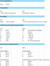
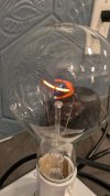
I replaced all damaged components with the original parts from another A-1 board and built a dim bulb tester. Upon the receiver power on the 150W bulb either goes bright then goes dim, or just goes dim on and stays this way (see the picture). The speaker relay won’t engage. With the receiver running through the DBT I checked the voltages on test points and on the ElCap board. The right channel looks OK and I can dial in DC offset and Idle current, however there’s around +/- 40V flowing through the components on the different boards from the right channel. Below are the measurements I’m getting.
Any advise will be very much appreciated.
I hope some Yamaha A-1 experts here can help me troubleshoot a weird voltage issue with my receiver.
I attempted a recap/servicing on my A-1, which went well until the Electrolytics board, which was supposed to be the last one. I studied everything related to the subject on AK and after each replacement prior to ElCap board I managed to dial spot on DC offset and Idling current per service manual.
I am novice in receiver recapping, and made some stupid mistakes, such as not using DBT and using a regular screwdriver for the adjustments (I did not know any better but I’ve learned my lesson). While I tried to be very careful, I must have shorted something, which resulted in a blown fuse, along with the destruction on the left channel components - fusible resistor FR101, driver transistors TR135, TR133 as well as both output transistors TR1 & TR2. The other channel is fine.
I replaced all damaged components with the original parts from another A-1 board and built a dim bulb tester. Upon the receiver power on the 150W bulb either goes bright then goes dim, or just goes dim on and stays this way (see the picture). The speaker relay won’t engage. With the receiver running through the DBT I checked the voltages on test points and on the ElCap board. The right channel looks OK and I can dial in DC offset and Idle current, however there’s around +/- 40V flowing through the components on the different boards from the right channel. Below are the measurements I’m getting.
Any advise will be very much appreciated.