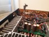
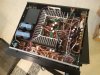
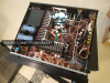
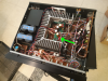
As a continuation of the thread: https://audiokarma.org/forums/index...ng-else-will-still-work.962306/#post-15203392 I've decided to develop a complete basic solution for power system modification in Yamaha A-1000 (A-700) and share it here.
This modification significantly improves the sound quality of the amplifier. The sound have higher resolution, it is cleaner, the separation of instruments and their sustain is improved. The dynamics and quality of high tones will improve. (I don't know Audiphile slang in English so they are just translated)
It works great with amplifiers with refreshed electrolytic capacitors.
The overall effect of improvement is always there, but the specific sound and tones characteristics are influenced by the capacitors used. Therefore, you should listen to several types of capacitors from different manufacturers and choose the best one for you.
I recommend using connectors like these:

to replace capacitors without soldering and solder them permanently only after choosing the ones you like.
In the Gerber zip file attachments there is a ready PCB design, which you can upload on the website of the PCB manufacturer, such as Chinese JLCPCB or others.
You are making modification at your own risk, so always measure the output voltages before installing in the amplifier and never change the + and - voltages.
Circuit additionally transfers about 2 x 5 Watt of power to the heat sink, so make sure you have a good connection with the heat sink. Components must be electrically insulated from the heat sink!
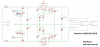
Schematic:

Wiring diagram:

Connect GND to central GND point on main board like is shown on diagram. I'm using Molex KK254 connectors or similar. The pcb board is designed for them.
What to remove from phono board:

Mounting:

PCB Gerber file: http://hifi-retro.vxm.pl/images/A-1000_PSU_MOD/A-1000 PSU Mod - HiFi-Retro for DIY.zip
PART LIST:
Voltage regulators
LM317/LM337 - Classic 3-Terminal Adjustable Regulator. I suggest improved types LT317/LT337 which have 3 times lover noise and better other parameters. TO-220
Transistors
T1 - NPN 20 Watts in TO220 package. Sanken 2SC4883 or 2SC4382 are a good choice.
T2 - PNP 20 Watts in TO220 package. Sanken 2SA1668 or 2SA1859.
it is important to use genuine parts due to the constant power load of about 5W per transistor. Fake products can fail.
Diodes
D11,D21 - 27V Zener diode 0,5W. Can be BZX55 low noise zener diode
D31,32,41,42 - 1N4002 or similar diodes.
Resistors
R10,R20 - 10 Ohm 3 W - To protect transistors from burning because of high current peak when turning on and high output capacitance.
R11,R21 - 5,6 kOhm
R31,R41 - 240 Ohm
R32,R42 - 3,92 kOhm for Yamaha A-1000 (22V) or 3,16 kOhm for A-700 (18V)
Use 0,5 W, 1% tolerance metal film resistors with 50 PPM/C or better for best results
Capacitors
C12,C22 - 100nF - 5mm lead spacing
C11,C21 - 220-330 uF / minimum 35V - 3,5mm lead spacing, 8mm diameter max
C13,C23 - 470-1000 uF / min. 25V - 7,5mm lead spacing, 18mm diameter max. You can hear a different types in sounding, but not so much as Cadj and output capacitors.
C31,C41 - 100nF - 5mm lead spacing
C32,C42 - 10-22 uF / min. 25 V - 2,5mm lead spacing, 6mm diameter max. Cadj capacitors. Very important for sounding and overall performance.
C33,C43 - 10-22 uF / min 25V - 2,5mm lead spacing, 6mm diameter max. Output small capacitors close to the Ic's. Important for sounding
Cout+,Cout- - 1000 uF / min. 25V - 7,5mm radial or 10mm Snap In lead spacing, 22mm diameter max. Very important for final sounding and overal performance
I recommend using 50V capacitors because they usually sounds better.
You can also watch my modified Yamaha A-1000 on this video:
Enjoy!
This modification significantly improves the sound quality of the amplifier. The sound have higher resolution, it is cleaner, the separation of instruments and their sustain is improved. The dynamics and quality of high tones will improve. (I don't know Audiphile slang in English so they are just translated)
It works great with amplifiers with refreshed electrolytic capacitors.
The overall effect of improvement is always there, but the specific sound and tones characteristics are influenced by the capacitors used. Therefore, you should listen to several types of capacitors from different manufacturers and choose the best one for you.
I recommend using connectors like these:
to replace capacitors without soldering and solder them permanently only after choosing the ones you like.
In the Gerber zip file attachments there is a ready PCB design, which you can upload on the website of the PCB manufacturer, such as Chinese JLCPCB or others.
You are making modification at your own risk, so always measure the output voltages before installing in the amplifier and never change the + and - voltages.
Circuit additionally transfers about 2 x 5 Watt of power to the heat sink, so make sure you have a good connection with the heat sink. Components must be electrically insulated from the heat sink!
Schematic:
Wiring diagram:
Connect GND to central GND point on main board like is shown on diagram. I'm using Molex KK254 connectors or similar. The pcb board is designed for them.
What to remove from phono board:
Mounting:
PCB Gerber file: http://hifi-retro.vxm.pl/images/A-1000_PSU_MOD/A-1000 PSU Mod - HiFi-Retro for DIY.zip
PART LIST:
Voltage regulators
LM317/LM337 - Classic 3-Terminal Adjustable Regulator. I suggest improved types LT317/LT337 which have 3 times lover noise and better other parameters. TO-220
Transistors
T1 - NPN 20 Watts in TO220 package. Sanken 2SC4883 or 2SC4382 are a good choice.
T2 - PNP 20 Watts in TO220 package. Sanken 2SA1668 or 2SA1859.
it is important to use genuine parts due to the constant power load of about 5W per transistor. Fake products can fail.
Diodes
D11,D21 - 27V Zener diode 0,5W. Can be BZX55 low noise zener diode
D31,32,41,42 - 1N4002 or similar diodes.
Resistors
R10,R20 - 10 Ohm 3 W - To protect transistors from burning because of high current peak when turning on and high output capacitance.
R11,R21 - 5,6 kOhm
R31,R41 - 240 Ohm
R32,R42 - 3,92 kOhm for Yamaha A-1000 (22V) or 3,16 kOhm for A-700 (18V)
Use 0,5 W, 1% tolerance metal film resistors with 50 PPM/C or better for best results
Capacitors
C12,C22 - 100nF - 5mm lead spacing
C11,C21 - 220-330 uF / minimum 35V - 3,5mm lead spacing, 8mm diameter max
C13,C23 - 470-1000 uF / min. 25V - 7,5mm lead spacing, 18mm diameter max. You can hear a different types in sounding, but not so much as Cadj and output capacitors.
C31,C41 - 100nF - 5mm lead spacing
C32,C42 - 10-22 uF / min. 25 V - 2,5mm lead spacing, 6mm diameter max. Cadj capacitors. Very important for sounding and overall performance.
C33,C43 - 10-22 uF / min 25V - 2,5mm lead spacing, 6mm diameter max. Output small capacitors close to the Ic's. Important for sounding
Cout+,Cout- - 1000 uF / min. 25V - 7,5mm radial or 10mm Snap In lead spacing, 22mm diameter max. Very important for final sounding and overal performance
I recommend using 50V capacitors because they usually sounds better.
You can also watch my modified Yamaha A-1000 on this video:
Enjoy!
Last edited:

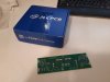
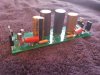

 Your Yamaha A-1000 has already had the capacitors replaced, so everything has to be adjusted (by correct selection of capacitors) for the best results and your hearing.