• The move to the new server is done. There are some software and database maintenance updates in process. This has us passing the hat around to help out. We appreciate any donations. Seriously, even a dollar helps. The payment page may be found here - https://www.audiokarma.org/support.html

Yamaha A-1000, A-700 PSU Modification - Complete Basic Solution

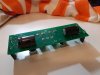
It seems that the defect, although serious, can be easily repaired. Probably due to a short circuit with the heat sink, the transistor burned and gave full supply voltage to the capacitor, which fired due to exceeding the maximum voltage. There is a transistor, a capacitor and probably a zener diode to be replaced. Check r10 and r11 resistors. The LM317 should rather be fine, I used to have a similar adventure in my layout and the LT317 was fine after. And once again, I remind you that the transistors and lm's must be isolated from the heat sink and screws with the washer mentioned by @avionic

Thanks for the tips! In my new order for the special insulating washers, I will also order some of the different capacitors you mentioned earlier. I did some initial testing, and even though the LT317 was touching the heatsink, it seems as if T1 as burned out as all 3 of its legs test positive for continuity. I will also check the other components you mentioned.
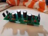
 
Ok I've done things better this time and used Nichicon UKZ, Panasonic FM-A, and Illonois KXM for the Cout.

01.jpg

0222.jpg
 
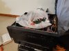
The plastic bag as an insulator works once again, the relay clicks after 2-3 seconds, it works! Now i just have to wait for the correct shoulder washers so i can install the board correctly...i ordered the wrong size previously.

plastic bag.jpg
 
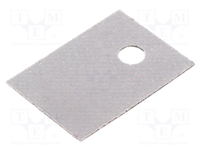
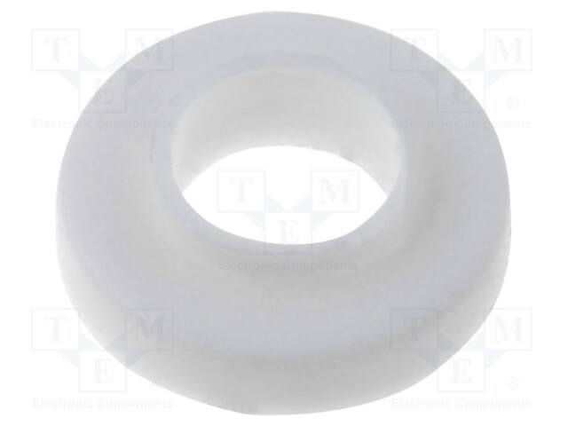
Good that is working again. To be sure, you need an insulating washer for the screw and a thermally conductive insulator for the TO-220 package. You have transistors with full plastic package now so you only need it for lm's. You can apply some termal condictive paste like for procesors under transistors.

451114_1.jpg


62592_1.jpg
 
Hi @bartek_k , your link is showing up broken for some reason. are you linking the image, or did you upload it? the images in your previous post seem to be working. But the images in your 1st post are also broken.
aaa.JPG

ddd.JPG


Images broken in your first post. When you get a chance, can you see if you can edit this post and upload the images? Thanks!
www.JPG
 
Hi, I am linking images but as i can see all of them are visible, even on another browser so maybe it was a temporary problem.

It must be my computer then...perhaps its time for me to do some updates. I can right-click on your image and open in new window and...
psuv52.jpg

Wow this is really over the top, you've really been busy!
 
I am taking my A-1000 out of storage after about 20 years. I want to put it in first class condition. Would it be possible to get from a list of the capacitors and other components that you used in your restoration. If so a listing of where you sourced them would also be of great help. I downloaded a copy of the service manual and printed the schematic to a large scale that I can read. Now I just need to upgrade my de-soldering and soldering skills. Thanks for any help that you can provide. Tim Baker in New Orleans
 
Old thread but if we are talking regulated psu mods then following may be of some interest, though read the fine print, only good upto abouts 100mA.
 
Back
Top Bottom