

You are using an out of date browser. It may not display this or other websites correctly.
You should upgrade or use an alternative browser.
You should upgrade or use an alternative browser.

tmsears
Active Member
Ok so I'm stupid. Since I conflated the last two steps together I had the output at 15.5 instead of 30....Try adjusting your time-base and volts per division.

Can you explain what the x-amp and it's setting does and if it is worth checking out you had a scope? That way if someone stumbles into here they will have it there to see?
Last edited:

What your checking is the rail voltage switching point.Ok so I'm stupid. Since I conflated the last two steps together I had the output at 15.5 instead of 30....
Can you explain on my thread what the x-amp and it's setting does and if it is worth checking out you had a scope? That way if someone stumbles into it they will have it there to see?

tmsears
Active Member
So thanks to the help of @zaibatsu and @avionic , I only have one or two loose ends I need to take care of:
1) the hum in the background.
2) the missing two volts on the negative side on step 2, the auto class A adjustment. When I turn the adjustment trimmer from the
+16v to the -16v, it doesn't go to -16, instead it goes to -13.66. New trimmer, old trimmer, doesn't matter, that's where it ends up at.
Is that something I should worry about or is the 2 volt difference fine?
(Update coming soon on the hum issue)
1) the hum in the background.
2) the missing two volts on the negative side on step 2, the auto class A adjustment. When I turn the adjustment trimmer from the
+16v to the -16v, it doesn't go to -16, instead it goes to -13.66. New trimmer, old trimmer, doesn't matter, that's where it ends up at.
Is that something I should worry about or is the 2 volt difference fine?
(Update coming soon on the hum issue)
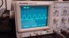
Using both channel 1 scope probe and channel 2 scope probe you can get both + and - traces on the sine wave.Update: I got step 3 done, the right way, here is what it looks like:
View attachment 950523 View attachment 950524
Looks spot on from what I can tell!


zaibatsu
yam
APS output looks mint!
By the way I found that thread, I think it was just a bit misleading because he calls Step 3 "a confirmation" straight after describing Step 2, not incorrect technically but he makes them sound related when they are not.
The -13.66 can't be normal, both values should be +/-16.xx
Those points are the voltages (for the top and bottom halves of the waveform) where the waveform would clip in Class-A mode, and instead of clipping, the "surplus" part of the wave is reproduced by the opposite device. That's my understanding anyway. So what your result means is that for the bottom half of the waveform your amp would be switching to AB at lower power output than it should be.
I'd be double-checking components in the Turbo sections / everything relating to IC102 and IC103.
Hopefully avionic has something more specific you can check.
By the way I found that thread, I think it was just a bit misleading because he calls Step 3 "a confirmation" straight after describing Step 2, not incorrect technically but he makes them sound related when they are not.
The -13.66 can't be normal, both values should be +/-16.xx
Those points are the voltages (for the top and bottom halves of the waveform) where the waveform would clip in Class-A mode, and instead of clipping, the "surplus" part of the wave is reproduced by the opposite device. That's my understanding anyway. So what your result means is that for the bottom half of the waveform your amp would be switching to AB at lower power output than it should be.
I'd be double-checking components in the Turbo sections / everything relating to IC102 and IC103.
Hopefully avionic has something more specific you can check.
tmsears
Active Member
APS output looks mint!
By the way I found that thread, I think it was just a bit misleading because he calls Step 3 "a confirmation" straight after describing Step 2, not incorrect technically but he makes them sound related when they are not.
I agree, I went back and read it again, and it is technically a "confirmation", just of a different thing. Context is everything I suppose
 .
.
tmsears
Active Member
The -13.66 can't be normal, both values should be +/-16.xx
Those points are the voltages (for the top and bottom halves of the waveform) where the waveform would clip in Class-A mode, and instead of clipping, the "surplus" part of the wave is reproduced by the opposite device. That's my understanding anyway. So what your result means is that for the bottom half of the waveform your amp would be switching to AB at lower power output than it should be.
I'd be double-checking components in the Turbo sections / everything relating to IC102 and IC103.
Hopefully avionic has something more specific you can check.
So I guess I will start rooting around the turbo amp section, hopefully Avionic will chime in because I am still very green with this stuff, much to the embarrassment of my family legacy. I am learning though. What you said before would have sound French to me only a few months ago, now, it is more like a heavily French-accented English!
Terrible humor aside, I guess maybe I should look at the resistors in the turbo section?
zaibatsu
yam
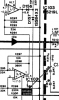
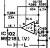
I'd check voltages along IC103 and IC102 first (see if they match schematic), careful with the meter leads.
Oh yeah and no hum is normal!
This stuff is Yamaha, lives would have been lost over something like that.
I'd start by going over all grounding points and bus bar solder joints (though you've probably already done that).
You can undo the 2 screws holding the main board to the chassis and hit the copper pads under them with some fine sandpaper.
Oh yeah and no hum is normal!
This stuff is Yamaha, lives would have been lost over something like that.
I'd start by going over all grounding points and bus bar solder joints (though you've probably already done that).
You can undo the 2 screws holding the main board to the chassis and hit the copper pads under them with some fine sandpaper.
Attachments

tmsears
Active Member
Well, may have a problem then, not sure. It has been a challenge for me to read the voltages on the schematics.
So, here are the results of what the I interpret the voltages are supposed to be, vs what they measure, are in parenthesis:
IC102 pinout voltages (actual):
1= 15.7 (16.12)
2= -0.3 (0.00)
3= 6.6 (6.77)
4= -16.9 (-16.94)
5= -7.5 (-7.88)
6= -7.6 (-7.52)
7= -15.5 (-15.66)
8= 16.6 (17.05)
IC103 pinout voltages (actual):
1= -26.5 (-0.03)
2= 0 (0.00)
3= 0 (0.00)
4= -17.0 (-16.94)
5= -0.3 (-0.33)
6= 4.7 (4.77)
7= -15.8 (-15.66)
8= 16.7 (17.05)
The measurements were taken after the amp had been running a while. I made sure it was idle with no load, no class A auto, no input.
So, here are the results of what the I interpret the voltages are supposed to be, vs what they measure, are in parenthesis:
IC102 pinout voltages (actual):
1= 15.7 (16.12)
2= -0.3 (0.00)
3= 6.6 (6.77)
4= -16.9 (-16.94)
5= -7.5 (-7.88)
6= -7.6 (-7.52)
7= -15.5 (-15.66)
8= 16.6 (17.05)
IC103 pinout voltages (actual):
1= -26.5 (-0.03)
2= 0 (0.00)
3= 0 (0.00)
4= -17.0 (-16.94)
5= -0.3 (-0.33)
6= 4.7 (4.77)
7= -15.8 (-15.66)
8= 16.7 (17.05)
The measurements were taken after the amp had been running a while. I made sure it was idle with no load, no class A auto, no input.
zaibatsu
yam
Your schematic reading matches mine and everything looks in-spec, except for Pin1 on IC103.
I'd probably check if Pin1 changes when the Class A switch is on, and if not, check that R298=390K and R294,R297=10K by lifting one leg.
My rookie ideas end there for now, but maybe it'll give avionic something to work with next time he's here.
I would probably focus on sorting out the hum issue first since the Class A thing probably won't make any audible change unless you plan to use the function AND have a difficult speaker load, most speakers and average listening levels shouldn't really even drive the amp to its switching point anyway.
I'd probably check if Pin1 changes when the Class A switch is on, and if not, check that R298=390K and R294,R297=10K by lifting one leg.
My rookie ideas end there for now, but maybe it'll give avionic something to work with next time he's here.
I would probably focus on sorting out the hum issue first since the Class A thing probably won't make any audible change unless you plan to use the function AND have a difficult speaker load, most speakers and average listening levels shouldn't really even drive the amp to its switching point anyway.
tmsears
Active Member
Sounds like a good plan. I kinda hope it works out as I have sorta grown fond of the class A operation during testing.Your schematic reading matches mine and everything looks in-spec, except for Pin1 on IC103.
I'd probably check if Pin1 changes when the Class A switch is on, and if not, check that R298=390K and R294,R297=10K by lifting one leg.
My rookie ideas end there for now, but maybe it'll give avionic something to work with next time he's here.
I would probably focus on sorting out the hum issue first since the Class A thing probably won't make any audible change unless you plan to use the function AND have a difficult speaker load, most speakers and average listening levels shouldn't really even drive the amp to its switching point anyway.

As for the grounding issue, I have been em working on it but with little success
 .
.I unhooked all of the input leads at the input selection board and that didn't change anything..... However, if I leave TAPE 1 and DAT unplugged the hum diminishes in intensity. The hum also reduces if I put my finger on either one of the copper ground rails. Since I had the bottom plate back off to check the IC's I looked over the board once more, particularly around the ground wire solder connections, and reflowed the solder connections' big blobs o' solder once more, adding as much 60/40 lead solder as I felt was safe. I had to go run an errand before I could see if that helped or not.
Haven't tried the sand paper trick yet but it is next on the list.
Last edited:
zaibatsu
yam
I did have an idea, put the amp back on the DBT (probably with 100W to be safe if you have one, otherwise your 150) and check if the relay clicks with the signal input plug disconnected from the power amp board (it's the one right at the front center between the two copper-foil polystyrene caps). On the A-700 it won't click in that guise because it requires the signal input to be grounded earlier, but I haven't tried it on my A-1000 (slightly different setup / layout) - if it does work, you could then directly connect the line input plug of your choosing (eg. DAD) straight into the power amp from instead of going into the input selector board (same plug / socket). This would bypass the flat amp board / tone circuits / volume pot / input selector / mute switch etc, and if the hum is still there you know it's a fault somewhere around those jacks or on the power amp board itself. You could see if the hum is there with nothing plugged in there also (probably first).
Just an idea, keep in mind with no volume control output will be at full volume so don't connect any inputs.
You could try just disconnecting ALL the inputs from the input selector board as well and see what that does.
You have reflowed the solder joints on the inputs (especially TAPE1 / DAD), and made sure there's no solder bridges on the soldered 3 pin connectors that come out from just behind the jacks I'm guessing?
On the Class-A thing, I haven't checked those +/-16V voltages on my own amp - but I'll check it out whenever I get it finished and running, just in case it's normal (or a factory fault).
Just an idea, keep in mind with no volume control output will be at full volume so don't connect any inputs.
You could try just disconnecting ALL the inputs from the input selector board as well and see what that does.
You have reflowed the solder joints on the inputs (especially TAPE1 / DAD), and made sure there's no solder bridges on the soldered 3 pin connectors that come out from just behind the jacks I'm guessing?
On the Class-A thing, I haven't checked those +/-16V voltages on my own amp - but I'll check it out whenever I get it finished and running, just in case it's normal (or a factory fault).
tmsears
Active Member
check that R298=390K and R294,R297=10K by lifting one leg.
My rookie ideas end there for now, but maybe it'll give avionic something to work with next time he's here.
I checked those, they were all within tolerance (391k,9.81k,9.82k). Hopefully @avionic will pop in and offer some guidance.