• The move to the new server is done. There are some software and database maintenance updates in process. This has us passing the hat around to help out. We appreciate any donations. Seriously, even a dollar helps. The payment page may be found here - https://www.audiokarma.org/support.html

Yamaha A 1020 repair

Alonia

Member
I have a Yamaha A-1020 standing here, which has a phenomenon that I have not seen before. When you turn it on everything is normal.
The relay switches after 3-5 seconds and you think you can use it. Unfortunately it is not so.
In the left channel there is a fluctuating voltage at the box connector that goes up to 50V+ and 50V-.
After a long search I decided to change the capacitors in the left channel first to exclude them as a source of error.
I also removed the glue on the board, which was used to fix the capacitors.
Unfortunately this did not fix the error. As a second step, I refreshed all soldering points to exclude cold solder joints.
Unfortunately this did not fix the error either.
After systematic measurements I came to the following conclusion.
The collector of transistor TR211 should normally have 1.7V+.
Here I don't measure 1.7V+ but fluctuating voltage of 50V+ and 50V-
(Here is a fault in the service manual. The voltages at the collector and emitter of transistor TR211 are swapped)

At the collector of transistor TR209 there should normally be 1.7V- available.
Here I also measure the fluctuating voltage of 50V+ and 50V-
I have measured this in the healthy channel on TR212 and TR210 and there the 1.7V+ and 1.7V- are present.

Here is a list, which parts I have replaced:
TR211
TR209
D211
D213
C231
C245
C243
C239
C213
C255

Function (4) is the small board at the cooler with the driver transistors.
I use the board from the right channel, which did not fix the fault.

Probably I overlooked a little something, which could solve the problem :(
I have attached an excerpt from the service manual and marked where the voltage fluctuates.
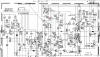
yamaha A-1020.png
 
Last edited:
Register to hide this ad
Here I also measure the fluctuating voltage of 50V+ and 50V-
Is there a "hard" switch in voltage for +50Vdc to -50Vdc or is it a gradual swing, eg, +50V, +40V, +30V,,,-40V, -50V.
Maybe 2 intermittent transistors.
Here is a list, which parts I have replaced:
TR211
TR209
What did you replace the transistors with? From a reliable source? (not ebay)
 
Is there a "hard" switch in voltage for +50Vdc to -50Vdc or is it a gradual swing, eg, +50V, +40V, +30V,,,-40V, -50V.
Maybe 2 intermittent transistors.

The voltage swing. +1,5V, +30V, +50V,,, -3V, -7V, ...

What did you replace the transistors with? From a reliable source? (not ebay)

I used KSA1013 and KSC2383 as replacements. I also used original transistors (2SA1145 and 2SC2705) from a working untouched yamaha RX-700 amp.
I have found this comparison type here in the forum in another post.
I generally only order parts from mouser and digikey. ;)
I've had three A-1020s on the table, all of which had a defective channel. I had never had this error until now :)
A master does not fall from the sky. :thumbsup:
 
Last edited:
If I see it right, TR234 and TR233 controls both channels. But then the error should be in both channels.
I struggled to work out what this circuit was doing, certainly others can do better. Thinking that one +/- voltage was being clamped
to 0V then switching over to the other, but working out what the circuit does??? will have another look later...
 
I struggled to work out what this circuit was doing, certainly others can do better. Thinking that one +/- voltage was being clamped
to 0V then switching over to the other, but working out what the circuit does??? will have another look later...

Unclear for me is how 1.7V is generated between TR011 and TR209.
Furthermore I can't quite interpret what TR207 does.
the rest in the Main AMP. is so far actually understandable for me.
Since I cannot quite understand this, it is difficult to find an approach.
I would now speculate that I have to look at TR203 and TR205 in connection with TR207.
I will measure the voltages on the transistors and compare them with the right channel.
 
UPDATE:
- I pulled the signal at the volume control to ground to isolate the error.
- I bridged the Class A button, because it has contact problems.

I have removed the following parts:
TR213 => 2SC3182
TR215 => "
TR219 => 2SA1265
TR217 => "
TR227 => 2SA970
R267 => 4,7ohm 1/4
R269 => "

I replaced these parts with new ones:
TR211 => 2SA1145 => with OEM part replaced. (part comes from a working Yamaha RX 700) => also replaced with a KSA1013
TR209 => 2SC2705 => with OEM part replaced. (part comes from a working Yamaha RX 700) => also replaced with a KSC2383
TR207 = 2SC1815 => with OEM part replaced. (part comes from a working Yamaha RX 700)
D211 => 1SS82 => replaced with a BAV21
D213 => 1SS82 => replaced with a BAV21
TR205 = 2SA970 => with OEM part replaced. (part comes from a working Yamaha RX 700)

I exchanged the function (4) board with the other channel. => The error still remains in the same channel.
The voltage between TR211 and TR209 is still oscillating. (-2V, -13V, 19V, -45V, 34V, ....)
Does anybody have an idea what it could be?


Yamaha A1020.png

On this picture I wrote down my measured voltages before I started to desolder or replace parts:
Yamaha A1020 schematic 2.png
 
...I exchanged the function (4) board with the other channel. => The error still remains in the same channel.
The voltage between TR211 and TR209 is still oscillating. (-2V, -13V, 19V, -45V, 34V, ....)
Does anybody have an idea what it could be?
Please measure and compare the 'feedback' resistance on both channels.
Also measure the value of R361.
Please post the results.

YAMAHA_A1020_Resistance.jpg

Viel Glueck!
 
Please measure and compare the 'feedback' resistance on both channels.
Also measure the value of R361.
Please post the results.

View attachment 2050668

Viel Glueck!

R361 -> 46,9ohm
I have already tested every 1/4W resistor „Flame proof Resistor“.

Rf L -> 6,79kohm
Rf R -> 4,25kohm

but the value continues to rise.
If I remove the measuring tip and put it back on, the resistance value starts again at the same value to rise.
Currently TR217 and TR213 are not soldered in.
 
Switch the TONE BYPASS switch ON and measure Rf on both channels.
Check C231 for damage.
Please post the results.

Viel Glueck!
 
Switch the TONE BYPASS switch ON and measure Rf on both channels.
Check C231 for damage.
Please post the results.

Viel Glueck!

I have already replaced all capacitors in the defective channel with Nichicon Findgold capacitors.

CF902F3D-4BFF-4538-A20C-8664BC33706B.jpeg

With Tone Bypass I measure the same values.
EDIT:
Rf L and Rf R rise slower and starts with the same values.
 
When Rf stops rising, what is the maximum value reached on each channel with 'TONE BYPASS' OFF and 'TONE BYPASS' ON?

Good Luck!

I have found the error. :)
The bass potentiometer has a hairline crack from the inside.
The channel has been disturbed by surrounding circuits and has swung itself up. :confused:
Thank you very much for the solution suggestions.:beerchug:
 
Back
Top Bottom