• The move to the new server is done. There are some software and database maintenance updates in process. This has us passing the hat around to help out. We appreciate any donations. Seriously, even a dollar helps. The payment page may be found here - https://www.audiokarma.org/support.html

Yamaha A-S2100 Stuck In Protection

H2s04

auralmicitisis
Hello fellow AKers,

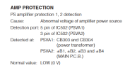
I was recently given the challenge to resurrect or at least diagnose what’s wrong with a Yamaha A-S2100 that’s stuck in protection. With the diag key command, it will enter limp mode and presents three flashes. According to the service manual, this indicates an abnormal voltage condition with “PS Amp 2.”

I haven’t been able to find much information about this amp other than people in similar situations asking others what to do, and being told to bring it to Yamaha (circa 2016.)

Tomorrow, I will attempt to get readings on the various PS rails and see if I can find anything that doesn’t line up. I’m wondering if anyone else here has had experience with this amp’s problematic nature. I think something like 16 conditions need to be met in order for it to pass its own startup cycle.

Ugh. I’m a bit in over my head here.

Thank you all for reading, would love to know more hat others have experienced with this amp.

-Jeff
 
Register to hide this ad
I think something like 16 conditions need to be met in order for it to pass its own startup cycle.

You can cancel the diagnostic function but you'd only want to do that after you've determined there's no serious damage in the amplifier channels. It won't let you cancel the diags if there's been an overcurrent trigger.

The amplifiers are pretty reliable in general. But the service manuals (schematics) are just putrid.

You are on the right track- check your supplies first. Some are resistor (fusible) dropped and I would be looking hard at the front end HV supplies for each amp.

Be very careful if poking around the micro- they cannot be replaced.

How is the interior condition? Dust and moisture is a real problem with modern Yamaha (full of SMD that is exposed, especially on the rear vertical boards) but that's unlikely the problem- just mentioning it. I have few written-off AS-xxxx products here but no 2100.
 
I have equal power on all 4 b+ rails as of this morning. Both channels operate and sound great in diag mode. Is there any way to fully clear error codes in order to get the amp to just operate normally? I agree with you, the service manual is not the greatest and a bit cryptic. Could this simply be something related to a PSVA1/2 connector not seating correctly somewhere in the amp’s chain of protection checks?

Thank you very much for your reply, by the way.

-Jeff
 
Did you check the following voltages +/- B1,2,3,4 and also voltages at those connectors CB303, 4
All these points should be near the main filter caps, see page 66 of sm.
 

Attachments

  • AS2100.png
    AS2100.png
    33.5 KB · Views: 15
Did you check the following voltages +/- B1,2,3,4 and also voltages at those connectors CB303, 4
All these points should be near the main filter caps, see page 66 of sm.
Hi there! So I checked all B+ rails and they are identical. I found that at PSVA2 there is a -5v pulse for about 2 seconds on startup which I would imagine would cause IC502 to lock up. I traced the PSVA2 signal back to MAIN 3 the power board with the 4 tank caps. I’m going to take that board out today to check diodes, rectifiers, and opto couplers. I have a feeling I won’t find anything though. Hmm.
 
I am completely stumped, and getting very depressed due to this process. I can’t find an answer. I have rent money on the line based over if I can fix this thing or not.

Zero idea as to what to do.
 
I work on electronics but don’t have roadmaps of your amp but if it goes into protection after the self test to click on relays. It’s detecting a short. Common are the preamp fets should be one single on each channel or the main outputs 2 or four etc. three legged tests to ground and to each pin. It Only takes one. A lot of amps almost always shorted a leg to itself like 80-90 percent of the amps I ran across. Maybe give you some direction.. also remember you have the same circuits on both sides L and R. If you don’t know the value, check with the other side. I’m sure you checked but speaker connector not shorted to case, and/or Nothing jammed in one of them. Had one shorted out on the case before tripping protection.
 
Last edited:
I haven't worked on this piece but have a little experience on newer pieces. This SM is a headache first off.
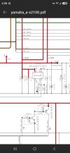
I'd check Voltage at Q303 on page 81 Main (3). Might be easier to test it at CB 32. It's the best (and only) divide & conquer point I can find in this digital maze. Maybe you'll get lucky & find CB32 loose or dirty in the process for a quick fix. Cycle it.

Good luck with that one, yikes.
Screenshot_20260903_190159_DuckDuckGo.jpg
 
Last edited:
Yeah, I've had a look at this a few times and I'm struggling, best I can come up with is that Q303 is part of the health check of the opto-couplers. Regarding CB32 could you do the following,
- PSVA2 pin confirm you are getting the 5V dip as previously described
- +5s pin monitor this pin, is it stable or ??? during attempted power up

Also monitor voltage on one side of R339 during power up.

Again, the guess is one of the opto-couplers has failed but you flagged this in an earlier post and presumeably checked these out.
 

Attachments

  • R339.png
    R339.png
    109.4 KB · Views: 4
Why do you think it’s the front protection side? Any over voltage as your pressing standby? DC feeding back? Bad diode? Does your unit have the self test diag? Flashing standby light flashing codes etc? Dc should be like .33-.90. Any higher it clicks over. Oh it does. I just read it.. you have amp 2 - 3 flash’s. Power supply getting voltage on that side, fuses of course, volume knob fubared stuck at a high volume something dumb I’ve had in the past. And hoping you tried unplugging it for 30 mins just to see if it cleared it out. Just wondering what happened the first time getting into protection mode. Etc. I’ve had PSUs board just die from electric out and coming back on even with the unit off, just plugged in.
 
Last edited:
Hello all, thank you deeply for getting back to me on this project. I had to take a short break to clear the mind and return to it. I have a suspicion that the protection circuit is actually doing its job correctly. I observed that there’s about 90 to 70mV of DC on the left channel as opposed to about 8mV of DC on the right channel. The first time I powered this unit up (was given to me by a friend to fix, I’m not sure if this amp’s history) the left channel didn’t actually work in diag mode. Second time I fired diag mode, the left channel came to life. I’m thinking there’s something in the left channel board that is dragging down a rail during startup which triggers PSVA2 to fire the 5v 2 second pulse.

I took out main (3) (board with the tank caps) and checked all diodes I could reach, checked the opto couplers (only could get a reading on one side for each of them) and checked cap values. I actually observed two bad solder joints on the 3300uF caps, repaired those, but no difference came about. I have also observed that if I disconnect CB301 (left channel feed) the amp begins to come to life with VU meters at 100% brightness for about 4 seconds before a full power off. If I go into diag mode with CB301 disconnected, the 3 flash code is now a 2 flash code. Reconnect and we go back to 3 flashes.

Everyone- I again deeply, deeply appreciate your input here. I’m sorry to have gotten emotional but when I can’t find hope in a project, it has some negative effects on my mind sometimes. I care so much about getting this thing to work, for personal reasons beyond the rent money thing.

For now, I’m going to go on the assumption that assumption that main (3) is an ok board. Power transformer also checks out. I really feel like given the DC offset issue on the left channel, that I need to take out both L and R and begin comparing values of FETs, etc.

My next move is to scope the rails on startup and compare if there’s any bogging down on the left feed compared to right.

Hopefully by tomorrow I’ll have some more information and answers.

Thank you again,

-Jeff
 
  • Like
Reactions: mbz
Hello all, thank you deeply for getting back to me on this project. I had to take a short break to clear the mind and return to it. I have a suspicion that the protection circuit is actually doing its job correctly. I observed that there’s about 90 to 70mV of DC on the left channel as opposed to about 8mV of DC on the right channel. The first time I powered this unit up (was given to me by a friend to fix, I’m not sure if this amp’s history) the left channel didn’t actually work in diag mode. Second time I fired diag mode, the left channel came to life. I’m thinking there’s something in the left channel board that is dragging down a rail during startup which triggers PSVA2 to fire the 5v 2 second pulse.

I took out main (3) (board with the tank caps) and checked all diodes I could reach, checked the opto couplers (only could get a reading on one side for each of them) and checked cap values. I actually observed two bad solder joints on the 3300uF caps, repaired those, but no difference came about. I have also observed that if I disconnect CB301 (left channel feed) the amp begins to come to life with VU meters at 100% brightness for about 4 seconds before a full power off. If I go into diag mode with CB301 disconnected, the 3 flash code is now a 2 flash code. Reconnect and we go back to 3 flashes.

Everyone- I again deeply, deeply appreciate your input here. I’m sorry to have gotten emotional but when I can’t find hope in a project, it has some negative effects on my mind sometimes. I care so much about getting this thing to work, for personal reasons beyond the rent money thing.

For now, I’m going to go on the assumption that assumption that main (3) is an ok board. Power transformer also checks out. I really feel like given the DC offset issue on the left channel, that I need to take out both L and R and begin comparing values of FETs, etc.

My next move is to scope the rails on startup and compare if there’s any bogging down on the left feed compared to right.

Hopefully by tomorrow I’ll have some more information and answers.

Thank you again,

-Jeff
Its cool.. Just wanna say, I may not have the correct English at times and I’m sorry for that. Lmao. But reading this things pop in my head.

I don’t jump into any roadmaps until I find a clue, burnt chip, missing voltage or shorts. Ok that said.

Follow your power from transformer to your rails but as you do that, I think you must turn off the unit and turn it back on each time. If the diag mode bypasses the faults then you won’t have to.
Follow that voltage to your amp 1 and 2. And see what’s missing, or what’s low voltage. I’m assuming it didn’t pop anything else while in diag mode so you should see your voltages stable. If they are, psu and current is there, thermocouple fuse and line fuse good etc. not sure if it has a thermo fuse but it might. If you have voltages on both sides, then you know you’ll have to dig deeper. Fets etc. but if your missing voltage then you know to stop and start looking at your schematics.

I don’t do a lot of amps I do mainly laptop and pc main boards, GPUs, hvac control boards and appliances. Some crazy things here and there, amps once in awhile only because by the time we get them they are so cooked they arnt worth fixing. Lower end consumer 2x100 Sony receivers etc. 200-300$ receivers basically.

I also jumping in because you needed your rent paid so just wanted to maybe jog your mind if you missed anything. Never know you can go down a rabbit hole. I try to keep things as simple as it gets for diag. That’s just me. ❤️

If you got a thermocamera use it.. very helpful to see what’s powered up, off or short. My goto tool..
 
Last edited:
  • Like
Reactions: mbz
I observed that there’s about 90 to 70mV of DC on the left channel as opposed to about 8mV of DC on the right channel.
While not ideal 70-90mV DC offset unlikely to cause protection issue.

I have also observed that if I disconnect CB301 (left channel feed) the amp begins to come to life with VU meters at 100% brightness for about 4 seconds before a full power off. If I go into diag mode with CB301 disconnected, the 3 flash code is now a 2 flash code. Reconnect and we go back to 3 flashes.
2 Flashes indicates a Power Supply problem (not a DC offset issue).
Disconnecting CB301 kills +/-56V for both L&R channels. The unit detects this via sense resistors R316,7 and feeds the result (via the green line) to the PRV (Protection, Voltage) pin on CB32, later to MCU who detects PRV out of range. This is normal behaviour.

Please reconsider the measurements/actions in post #10

Why sulphuric acid?
 
Yeah check what MBZ is telling you if he has some experience on this model for sure.. I’m giving you basic amp failures that I see over and over. Amps are all built pretty much the same with a few differences, but the basics are still there.

. Maybe he’s a chemist or likes cleaning things to the bone.

This three flash code is ps amp protection 2 “right side” which is showing either a short on the voltage rail “lower then normal 50volt etc” or a high voltage “like failed diodes” and clicks off the relay. If that makes sense. Just remember short will take out power transistor, diodes and caps in the rail that feeds it voltage. If you do find a bad transistor fet, make sure you check all the way back to the main power rail and test each component. don’t just swap out the bad one and never check the other components going backwards. They take the fall too.. I do think there’s a power transistor or three gone tho. Plus a cap or two in the feed chain.

Opto sensors do fail or start failing which would move your 50volt high or too low too. It’s the voltage control for the rail.

If you’re going to pull the tanks and heat sinks out, as your pulling connectors see if any are loose, or a pin backed out of a connector. That shet happens just out of the blue. Bass shakes the connectors for 4 yrs etc. keep an eye out for the easy over looked shet!

I wonder if there’s a board view of this unit? That’s all I use for pc gpu. You can follow traces pretty easy with the software.
 
Last edited:
Slowly getting my head around the schematic.

I'd scratch the idea of faulty opto-couplers as this would cause a PSVA1 error. Monitoring voltage at R339 would confirm, note one side is GND, wanting otherside of R339 to be +0.6Vdc abouts, ie, Q304 = ON

For PSVA2 candidates are Q303,2,1 D309, D310, these are SMD and mounted on the SMD side of the board so difficult access. The unit does not appear to have a removeable base plate so would need to remove the MAIN(3) board = major PITA. Looking for +4.4Vdc at diode anodes and +3.8V at cathodes
 
I finally found the +5V regulator, IC504. It goes to the emitter of Q303 (+5S) as well so it's a must check, and should be easier to access because it's on the A side of the function 1 board.
Test pin 3 Vout of IC504 (+5S) . I would test C534 while in there too...and it's +5M IC506 regulator buddy. But I'm leaning toward IC504. See SM page 77 J-7 photo attached, and page 58 G-4 for reference.

Sidenote edit: 5 volt regulator failures are common on many pieces in my digital experience. Also noticed this from other techs working on newer stuff. Regs and loose ribbon cables.

Screenshot_20260905_022840_DuckDuckGo.jpg
 
Last edited:
  • Like
Reactions: mbz
Everyone- I again deeply, deeply appreciate your input here. I’m sorry to have gotten emotional but when I can’t find hope in a project, it has some negative effects on my mind sometimes. I care so much about getting this thing to work, for personal reasons beyond the rent money thing.
We'll fix this. It's just a machine. All that emotion just clouds up the troubleshooting process. Mbz & I aren't writing novels here, we're just focused on the matter. So...
OIP-2413616108.jpg
 
Last edited:
Hopefully it's not too late to say but...strongly recommend ESD grounding wrist straps throughout our work here. Many static sensitive parts within.
 
Hello all!

Back at it again trying to diagnose this complex beast.

Per Soundscape’s recommendation, I tested the voltages coming from the 5V regulator IC504. It’s going to sound absurd but I’m not sure of the pinout of this particular regulator, but the voltages I collected are: 5.22V, 4.42V, 4.44V, and around 4mV. Could someone shed light on whether or not these voltages seem in range of what they should be? If 5.22V is the 5+ supply, it seems a bit high, right?
 
Back
Top Bottom