• The move to the new server is done. There are some software and database maintenance updates in process. This has us passing the hat around to help out. We appreciate any donations. Seriously, even a dollar helps. The payment page may be found here - https://www.audiokarma.org/support.html

Yamaha A1 integrated amp (phono issue)

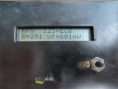
Got a new battery for my component tester. So here are the values (in random order) of the old, original transistors.

D786 NPN
B 292 - Uf 596 mV
B 291 - Uf 592 mV
B 438 - Uf 592 mV
B 291 - Uf 592 mV

B737 PNP
B 149 - Uf 607 mV
B 127 - Uf 614 mV
B 135 - Uf 615 mV
B 123 - Uf 616 mV

Looks like on of the NPN transistors has a higher gain value compared to the three others. The other three have very close values.
The PNP transistors have a wider range of values, with one at +15%.
 
Last edited:
Got a new battery for my component tester. So here are the values (in random order) of the old, original transistors.

D786 NPN
B 292 - Uf 596 mV
B 291 - Uf 592 mV
B 438 - Uf 592 mV
B 291 - Uf 592 mV

B737 PNP
B 149 - Uf 607 mV
B 127 - Uf 614 mV
B 135 - Uf 615 mV
B 123 - Uf 616 mV

Looks like on of the NPN transistors has a higher gain value compared to the three others. The other three have very close values.
The PNP transistors have a wider range of values at around, with one at +15%.
What is being measured here? What’s Uf?
 
Here is the schematic of the Tranny's he replaced, It would have been nice if he labeled where each transistor was taken from ie. TR 301 had this value etc.

55201256183_b0b04e73c9_h.jpg
 
Last edited:
Uf should be the base-emmiter voltage drop, no?
And B is gain (hFE).
Ok, there’s nothing really wrong about these numbers, they look fine. That one hFE is also not unheard of, it happens. Absent more data/tests, these numbers don’t indicate a problem.
 
Here is the schematic of the Tranny's he replaced, It would have been nice if he labeled where each transistor was taken from ie. TR 301 had this value etc.

55201256183_b0b04e73c9_h.jpg
Nash, The image here isn’t displayed properly, at least at my end anyway … just a black square with a question mark in the middle.:dunno:
 
Nash, The image here isn’t displayed properly, at least at my end anyway … just a black square with a question mark in the middle.:dunno:
You know, this has been happening lately and not sure why. But I can see it. Let me edit it again and see if it shows up for you.

Athanasios
 
Ok, there’s nothing really wrong about these numbers, they look fine. That one hFE is also not unheard of, it happens. Absent more data/tests, these numbers don’t indicate a problem.
OK. How can I test the transistors in order to identify the faulty one?

There was a real problem, as shown in my video on the previous page, and it's definitely gone. Overall the amp is very quiet now. When no record is spinning, you can only start hearing background noise at volume level 7 or 8. Before, the speakers were popping at level 2 or 3, not more. No source playing, only the amp powered on (on phono MC), without touching any switches or pots.

Link to my initial post with the video: Yamaha A1 integrated amp (phono issue)
 
OK. How can I test the transistors in order to identify the faulty one?
I guess you’d need a curve tracer to test them under various bias conditions (Vce, Ic, etc.). Sometimes the transistors pass under light conditions of commercially available testers but fail under real circuit conditions. Also need to run tests over temperature, as the circuit and the transistor warms up, some faults may act up.

Of course you might have corrected some solder joint issues in the process of changing transistors too. I’d just let it be, it isn’t worth the time and expense to find out. Even if you had the equipment (I’m just assuming you don’t, I may be wrong), you’d need to know how to use it. Just enjoy the music is what I’d recommend. :biggrin:
 
I think that would be a good bet.

SWAG . B represents Beta. (gain)
Yes, it does indeed. It’s not, however, the same as hFE. Beta is the general DC current gain, hFE is the DC current gain in common emitter configuration. Not exactly interchangeable.
 
I guess you’d need a curve tracer to test them under various bias conditions (Vce, Ic, etc.). Sometimes the transistors pass under light conditions of commercially available testers but fail under real circuit conditions. Also need to run tests over temperature, as the circuit and the transistor warms up, some faults may act up.

Of course you might have corrected some solder joint issues in the process of changing transistors too. I’d just let it be, it isn’t worth the time and expense to find out. Even if you had the equipment (I’m just assuming you don’t, I may be wrong), you’d need to know how to use it. Just enjoy the music is what I’d recommend. :biggrin:

As you guessed, this is way out of my reach. :)

I was just curious if it was only one transistor that had gone faulty, or if all were on their way out. I think it was bettere to change all in order to have matching pairs on both channels. And yes, the problems was certainly heat related. The solder joints looked good overall, nothing suspicious. ;)

Fun fact, I found the MC sound to be a bit dull, with a rolled-off top end, after the repair. I have a Denon DL-103 on my Sansui SR-929 turntable. I remembered that I switched the phono cable for a new one when reconnecting everything. So I put the old cable back in place, the one that originally came with the turntable, and the highs are back 8)
 
Last edited:
Fun fact, I found the MC sound to be a bit dull, with a rolled-off top end, after the repair. I have a Denon DL-103 on my Sansui SR-929 turntable. I remembered that I switched the phono cable for a new one when reconnecting everything. So I put the old cable back in place, the one that originally came with the turntable, and the highs are back 8)
Contrary to common belief, cables and wires make a huge difference in sound quality. For turntables, it’s even more so because every cable has its own capacitance. Anyway, glad things worked out, enjoy.
 
I have a Denon DL-103 on my Sansui SR-929 turntable. I remembered that I switched the phono cable for a new one when reconnecting everything. So I put the old cable back in place, the one that originally came with the turntable, and the highs are back

This problem is strange; usually MC cartridges are little or not at all affected by the capacitance of the phono cables, always maintaining the same high frequency response, unlike MM cartridges which are very sensitive to the pF of the cable with steep drops starting from about 10/12 kHz and above.
 
This problem is strange; usually MC cartridges are little or not at all affected by the capacitance of the phono cables, always maintaining the same high frequency response, unlike MM cartridges which are very sensitive to the pF of the cable with steep drops starting from about 10/12 kHz and above.
Some time cables go high in resistance from solder connections degrading at the connectors . I had a poor sounding TT and measured the capacitance and ohm and it read 680 ohms on one channel!!!! it was the solder connection breaking away from the connector .

Athanasios
 
Some time cables go high in resistance from solder connections degrading at the connectors . I had a poor sounding TT and measured the capacitance and ohm and it read 680 ohms on one channel!!!! it was the solder connection breaking away from the connector .

Of course, this can happen too; it is necessary only to restore the welds
 
Back
Top Bottom