• The move to the new server is done. There are some software and database maintenance updates in process. This has us passing the hat around to help out. We appreciate any donations. Seriously, even a dollar helps. The payment page may be found here - https://www.audiokarma.org/support.html

Yamaha B-1 Quickie

Yes sir...I think but surely I'm wrong that the best thing was setting the new trimmer with the value of the old ...The old trimmers have the original Yamaha setup. And if everything is OK there should not be any problems, IMHO ...:)
Yes indeed Beau Geste! It's certainly a good place to start assuming no one has been there yet.
 
Yes sir...I think but surely I'm wrong that the best thing was setting the new trimmer with the value of the old ...The old trimmers have the original Yamaha setup. And if everything is OK there should not be any problems, IMHO ...:)

sure that is a good approach. However, it did not have the original Yamaha settings. The gentleman that sold me the unit told me that the unit was at Sounsdmith in NY for some adjustments. The unit was running horrendously hot when I got it. The last thing I wanted was to reproduce that old setup. Besides, I replaced a bunch of components including a bunch of semis, including some on the driver boards, some with much higher gain.

What I did, I either turned the pots all the way to the left, or to the mid point, depending of Yamaha's recommendations. Where I used slightly different values (e.g. 20k vs 22k, or 500 vs 470r, I turned the pots to mid point value of the original value, then I soldered them to the boards. In my case the "Quickie" while not a full rehab, it was quite extensive. Starting with a tabula rasa setup and adjust from there, was the decision for me.

 
Yes indeed Beau Geste! It's certainly a good place to start assuming no one has been there yet.
Exactly, sir assuming that there were no adjustments before.But generally nobody does it because they are focused on the components and also because they often do not have adequate equipment. This is a trick I always use. It always works. If everything is ok, welding, components, etc. there should not be problems. I always write the value of the trimmers when I replace them. And in any case the setting is really minimal in one way or another (+ or -)
 
sure that is a good approach. However, it did not have the original Yamaha settings. The gentleman that sold me the unit told me that the unit was at Sounsdmith in NY for some adjustments. The unit was running horrendously hot when I got it. The last thing I wanted was to reproduce that old setup. Besides, I replaced a bunch of components including a bunch of semis, including some on the driver boards, some with much higher gain.

What I did, I either turned the pots all the way to the left, or to the mid point, depending of Yamaha's recommendations. Where I used slightly different values (e.g. 20k vs 22k, or 500 vs 470r, I turned the pots to mid point value of the original value, then I soldered them to the boards. In my case the "Quickie" while not a full rehab, it was quite extensive. Starting with a tabula rasa setup and adjust from there, was the decision for me.
Well, it seems to me that you have other B1and or B2 take the values from these. :)
 
Well, it seems to me that you have other B1and or B2 take the values from these. :)
while that is not a bad idea, I think that I rather start from scratch with everyone of them...Think of it as working with a standard or a starting point. It is much easier to start from one end than to drop in somewhere in the middle of a range.
Your approach would work best if I were to replace just the pots in a unit that was already working to spec
 
Last edited:
Okie, so I think I am dunn with adjusting this beast.

Factory spec for performing THD adjustment:
Idling current - 80mV
Signal generator feed - 20kHz
Amp load - 8R
Amp amplitude - 30dBm (or 75W)
Ideal THD <0.06%

Actual result for this amp - THD< 0.016% on both channels (@ 30dBm)

@ 30dBm, the current between O and TP goes to ~300mA. Once the load and generator are decoupled, the current between O and TP goes right down to 80mV. Have been running the beast at 30dBm for over an hour now. The heatsinks are at a toasty 160deg f. The idling current has not drifted a smudge. I guess that going the extra mile and replacing all carbon film to all metal film resistors on the driver boards is paying off.


IMG_20171227_222636212_HDR.jpg IMG_20171227_003144101_HDR.jpg


additional B-1 trivia:
at idle, the B-1 draws about 250W form the mains
with 8r load and @75W, it draws just under 600W

Overall it was a fun journey, with both, pain and excitement. I am now ready to start on a full rebuild, albeit, it will be a while until I'll find the time.

MANY THANKS to Vint Age for his technical expertise and for his patience!
Thanks to everyone else for their support!
 
Last edited:
I didn't do much but you're very welcome and thank you for sharing your journey! Hopefully this B-1 will give you back many years of wonderful sonic pleasure! :thumbsup: :)


I sure will enjoy it for many years.

Based on the limited time I had with the B-1 so far, It is the best amp I listen to so far. I will eventually set it up with a proper source and room layout at some point in the future, but these are my initial thought when comparing it to my other amps on duty:

My MX has balls to the walls, pushes well over 300W and its sound is crystal clear at any listning levels. The B-2 is sweet as a peach and a pleaseure to listen to, nice and smooth musical sound. .....
Neither of the two can do what the B-1 can with a set of speakers. I specifically used it to play a fast, bass heavy mix straight from my phone. No pre, no tone control, nothing. That usually sounds awful on my other amps including the B-2 which is very forgiving. The B-1 sounds fantastic because of the ease of control it has over the speakers at any frequency. I first used it on my crappy and sacrificial test speakers, then hooked it up to a set of NS-1000. Who says the B-1 is shy on highs, needs to have their B-1 restored. Who says that the NS-1000Ms are bass shy, they need to hook them up to a B-1. :D:D:D
 
Last edited:
Looked at the UC-1 service manual briefly. Has anyone here worked on one?
@clinic-audio , do I need the RU-1 connector cable in order to complete the final adjustments???

I have never seen an RU-1 cable for sale...ever. I am thinking that I could make one if I had the proper connectors...and if it is necessary for the final adjustments.
Anyone aware if these connectors are are some sort of a standard used for other applications?

@avionic , @Vint Age , are you aware of these connectors types?

Cheers,
Pete
 
Looked at the UC-1 service manual briefly. Has anyone here worked on one ? Yes , I did
@clinic-audio , do I need the RU-1 connector cable in order to complete the final adjustments ???
no , you don't need UC1 to adjust your B1 but you need a B1 to make all adjustments in your UC1
There is no difference between using an UC1 connected on the front of a B1 and using a B1 with UC1 through RU1
If you need a new couple of connectors you can replace both with actual models . The most important is to find connectors with same quantity of contacts and with the same size .
Don't forget also , that if you want to use your UC1 with RU1 you need to have the right B1 aluminium panel with rectangular hole ! very very difficult to find today !

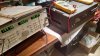
B1-front-plate-view-01.JPG
 
Looked at the UC-1 service manual briefly. Has anyone here worked on one ? Yes , I did
@clinic-audio , do I need the RU-1 connector cable in order to complete the final adjustments ???
no , you don't need UC1 to adjust your B1 but you need a B1 to make all adjustments in your UC1
There is no difference between using an UC1 connected on the front of a B1 and using a B1 with UC1 through RU1
If you need a new couple of connectors you can replace both with actual models . The most important is to find connectors with same quantity of contacts and with the same size .
Don't forget also , that if you want to use your UC1 with RU1 you need to have the right B1 aluminium panel with rectangular hole ! very very difficult to find today !

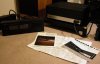
View attachment 1076339
Thank you!
as long as i do not need the cable to make the adjustments to the UC-1, then I do not care to have it or to make one.
Yes, a plate like that with be nice to have.
 
Looked at the UC-1 service manual briefly. Has anyone here worked on one?
@clinic-audio , do I need the RU-1 connector cable in order to complete the final adjustments???
The only place I've ever seen the RU-1 cable for sale is with a UC-1. Not sure who made those connectors (EDAC maybe¿) or where you'd find any these days.

Also, I don't think clinic read your question properly. Of course you don't need the UC-1 to set up a B-1; you already knew that. Albeit I've never adjusted a UC-1 but without that cable and the B-1 you'd have to get creative in how to power the UC-1 up and patch in the necessary input signals to calibrate it properly ...

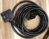
RU-1.jpg
 
Last edited:
Exactly, sir assuming that there were no adjustments before.But generally nobody does it because they are focused on the components and also because they often do not have adequate equipment. This is a trick I always use. It always works. If everything is ok, welding, components, etc. there should not be problems. I always write the value of the trimmers when I replace them. And in any case the setting is really minimal in one way or another (+ or -)
Little side question here. @Beau Geste , when you do it like that, between which legs are you measuring the value? Because you can measure 2 values: between 1 and 2 and between 2 and 3. Both willl give you different values. This becomes even more interesting when you replace a for instance original 2.2 kOhms pot with a 2 kOhms pot (when 2.2 kOhms is not available).

Capture.PNG
 
The only place I've ever seen the RU-1 cable for sale is with a UC-1. Not sure who made those connectors (EDAC maybe¿) or where you'd find any these days.

Also, I don't think clinic read your question properly. Of course you don't need the UC-1 to set up a B-1; you already knew that. Albeit I've never adjusted a UC-1 but without that cable and the B-1 you'd have to get creative in how to power the UC-1 up and patch in the necessary input signals to calibrate it properly ...

View attachment 1076344
I have not cracked the UC-1 open to see where the adjusting pots are located. I only looked at the sercice manual and I got the impression that I would need the RU-1 when adjusting UC-1, simply because the UC-1 would have to be with the hood opened when being calibtated, and if so, how can it also be connected to the B-1?
I think I will worry when I get to it. Maybe there is a way to do it without the cable.
 
I have not cracked the UC-1 open to see where the adjusting pots are located.
I just looked at the SM and it looks to me like you take off the UC-1 outer shell and once done you can still install it on the B-1 and access the adjustments through a top cut out in the UC-1 inner chassis.
 
I just looked at the SM and it looks to me like you take off the UC-1 outer shell and once done you can still install it on the B-1 and access the adjustments through a top cut out in the UC-1 inner chassis.
:thumbsup:

we'll find out all about it tonight
 
Back
Top Bottom