

You are using an out of date browser. It may not display this or other websites correctly.
You should upgrade or use an alternative browser.
You should upgrade or use an alternative browser.
Yamaha CA-610 restore or CA-1010
- Thread starter axxman
- Start date

axxman
Active Member
Thanks I have some heatsink ordered. I will take care of this later in the week. At least it does not appear the outputs are shorted.They all look Fine..Reinstall in there proper sockets. New heatsink compound recommended on both sides of the mica insulator . The old mica can be cleaned and reused.Mica doesn't tolerate much flexing..

Its likely a power supply or protect circuit issue.Will need to make a couple voltage checks at the amplifiers outputs..Then press on to other areas.At least it does not appear the outputs are shorted.
MonkeyRelish
Active Member
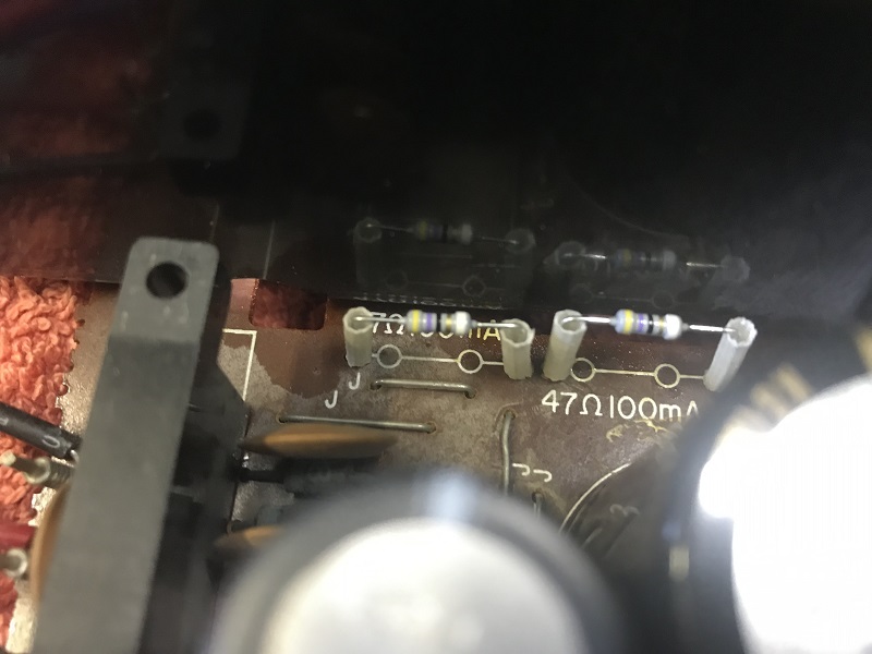
Just a thought, there are two 47 Ohm 100mA “fusisters” on the board.
They are the white things on the right. They are both 100mA fuse and 47 Ohm resister rolled into one.
Measure both, if they measure “open circuit”, then replace with Vishay 1/2 Watt 47 Ohm flame proof resistors.
Mr Relish
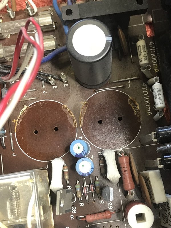
They are the white things on the right. They are both 100mA fuse and 47 Ohm resister rolled into one.
Measure both, if they measure “open circuit”, then replace with Vishay 1/2 Watt 47 Ohm flame proof resistors.
Mr Relish
Last edited:
axxman
Active Member
Update:
Thank you MR Relish and Avionic for your troubleshooting assistance. I received replacement fuzes. I installed one and turned it on. without speakers connected. Lights are back on and I hear the relay click. This still doesn't answer why it blew in the first place. Oh and I am using a dim bulb tester now until I know what the cause was. Since the problem occurred after I relocated the speaker wire connectors from terminal B to A, I plan to start there (with the unit unplugged) I use Pin terminated cables, similar to the "pins" on a multimeter. so I will just plug in one at a time and check for continuity between terminals and anywhere, however, I am starting to suspect the problem may have been my speaker cable connectors (see photo) I am thinking it may have been that one or both may have been touching. but if this were the case, wouldnt the speakers have suffered some damage, or wouldnt I have heard some horrible noise?
I also recieved some thermal grease. it is for computer heatsinks but I think it should be ok on my transistors, if there are no objections by Friday, I will proceed.
Once again thank you for your assistance, I will take measurments on the Fuisistors and post the results in the previous post so I can keep all measurements in one place.

Thank you MR Relish and Avionic for your troubleshooting assistance. I received replacement fuzes. I installed one and turned it on. without speakers connected. Lights are back on and I hear the relay click. This still doesn't answer why it blew in the first place. Oh and I am using a dim bulb tester now until I know what the cause was. Since the problem occurred after I relocated the speaker wire connectors from terminal B to A, I plan to start there (with the unit unplugged) I use Pin terminated cables, similar to the "pins" on a multimeter. so I will just plug in one at a time and check for continuity between terminals and anywhere, however, I am starting to suspect the problem may have been my speaker cable connectors (see photo) I am thinking it may have been that one or both may have been touching. but if this were the case, wouldnt the speakers have suffered some damage, or wouldnt I have heard some horrible noise?
I also recieved some thermal grease. it is for computer heatsinks but I think it should be ok on my transistors, if there are no objections by Friday, I will proceed.
Once again thank you for your assistance, I will take measurments on the Fuisistors and post the results in the previous post so I can keep all measurements in one place.
Not needed . The OEM's are flameproof.and fusible.I got 47.2 on both, I do like the idea of "flameproof"
axxman
Active Member
LOL mgkfifty you caught me just in time, I had just finished cleaning the first one and that little mica insulator. Ok, I will hold off until I hear back from the adults. I tried to find something for audio but I couldn't. This stuff came off pretty easy, it may have been serviced at some point.
Last edited:
Not plastic.. Its a mica insulator... What brand is that thermal grease?little plastic gasket
Gennel G104 is a safe non-electrical conductive product. Press on...
https://www.amazon.com/100Gram-Thermal-Grease-Silicone-Compound/dp/B019MSVEBY
Mica is a mineral crystal called muscovite.They do not tolerate excessive flexing.
Last edited:
axxman
Active Member
Ok here is the final result, not bad for my first time I think. the back half of the chassis is cleaned as good as I could get it without taking everything apart. this is most therapudic, especially when you have the other Yamaha on in the background.
I was very careful with the Mica pads, thevery last one had a little bend crossing the screw hole. I held it down at one end and wiped it one way only to avoid flexing.
ONCE AGAIN thank you for your help and guidance.
Here is the current status, I hope someday to recap everything and get the front half as clean as the back.
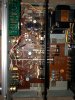
Here it is powered up, not connecting speakers tonight, couldn't handle the disappointment. I will give it a try tomorrow.
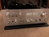
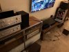
This is so sad yet wonderful, of the 3 Yamahas in this photo, the free one is getting the most use......the A-S801 will be my main driver but I want to run the CR-620 as much as possible before I take it to my home in Florida over Thanksgiving.

Next step assuming I don't blow it up when I connect speakers tomorrow.
I think the trick is to leave the cover off, as long as it thinks you are not finished, it behaves.
I don't know who I was trying to fool, all that work and not try it out......Hooked it up to the Bose 201 series 2 .....I can only listen at low levels but I am totally happy with them.
I was very careful with the Mica pads, thevery last one had a little bend crossing the screw hole. I held it down at one end and wiped it one way only to avoid flexing.
ONCE AGAIN thank you for your help and guidance.
Here is the current status, I hope someday to recap everything and get the front half as clean as the back.
Here it is powered up, not connecting speakers tonight, couldn't handle the disappointment. I will give it a try tomorrow.
This is so sad yet wonderful, of the 3 Yamahas in this photo, the free one is getting the most use......the A-S801 will be my main driver but I want to run the CR-620 as much as possible before I take it to my home in Florida over Thanksgiving.
Next step assuming I don't blow it up when I connect speakers tomorrow.
I think the trick is to leave the cover off, as long as it thinks you are not finished, it behaves.
I don't know who I was trying to fool, all that work and not try it out......Hooked it up to the Bose 201 series 2 .....I can only listen at low levels but I am totally happy with them.
Last edited:
axxman
Active Member
You are very observant.
Well since I cannot figure out how to attach the knobs securly, I think it is time for a little cleaning this evening. Photos coming shortly...
Ok, I cleaned as much as I could without dissassembling, just a soft bristle brush I had from computer cleaning. I will sleep better now
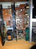
Close up of the phone section:
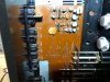
Right output section, this was really dirty but it came right off with the brush.

Closeup of the transformerI wiped the painted surface clean and lightly brushed the rest.
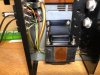
Power supply and protection circuit. This stuff is really tight so I just lightly brushed it clean.
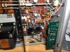
Close up of the inputs.
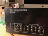
Closeup of the speaker terminals.

So the cover is going back on for now, it really sounds so good I dont want to touch anything at the moment. I would like to test what I can in circuit, if anything is out of spec, replace it, but I am so impressed with the sound I dont want to change anything. for now. I originally bought this amp as a interesting decorative piece but it has turned into a functional centerpiece. This may change when I have a chance to really crank it up, volume has not been about 30%.
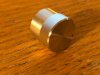
Next item up is pictured below, I have the knobs and these plastic things, however I guess with age, the knobs dont stay on, the plastic thingy on the balance wont come off, I have not tried pliers, or prying, I dont want to scratch anything. the loudness knob is outright loose. Does anyone have suggestions on how to get the knobs to stay, I am trying to avoid glue if possible as I probably dissassemble everything for cleaning at some point.
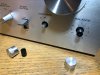
Well since I cannot figure out how to attach the knobs securly, I think it is time for a little cleaning this evening. Photos coming shortly...
Ok, I cleaned as much as I could without dissassembling, just a soft bristle brush I had from computer cleaning. I will sleep better now
Close up of the phone section:
Right output section, this was really dirty but it came right off with the brush.
Closeup of the transformerI wiped the painted surface clean and lightly brushed the rest.
Power supply and protection circuit. This stuff is really tight so I just lightly brushed it clean.
Close up of the inputs.
Closeup of the speaker terminals.
So the cover is going back on for now, it really sounds so good I dont want to touch anything at the moment. I would like to test what I can in circuit, if anything is out of spec, replace it, but I am so impressed with the sound I dont want to change anything. for now. I originally bought this amp as a interesting decorative piece but it has turned into a functional centerpiece. This may change when I have a chance to really crank it up, volume has not been about 30%.
Next item up is pictured below, I have the knobs and these plastic things, however I guess with age, the knobs dont stay on, the plastic thingy on the balance wont come off, I have not tried pliers, or prying, I dont want to scratch anything. the loudness knob is outright loose. Does anyone have suggestions on how to get the knobs to stay, I am trying to avoid glue if possible as I probably dissassemble everything for cleaning at some point.
Last edited:
Is the black plastic knob core pulling out of the aluminum knob sleeve?Well since I cannot figure out how to attach the knobs securely,
axxman
Active Member
Yes, see photo above.Is the black plastic knob core pulling out of the aluminum knob sleeve?
axxman
Active Member
One of my favorite you tube videos, no 2mm setscrew? Don't worry Avionic will be along soon to set you straight. If not PM him.
Yes, it especially sounds good through a CR-620. He was through my area a few months ago I should have gone to see him.
Place the "ruffed up**" black knob on the appropriate switch or control. Now gentilly rough up the inside surface of the aluminum knob.Set the black knob fully CW or CCW. Line up the aluminum red dot with the correct hash mark that is selected. Put a small bead of JB Weld around the bottom rim of the aluminum knob. Line up the red dot and correct hash mark and press away. The JB Weld will fully cure in 24 hours.Yes, see photo above.
** roughed up with # 80-120 grit.sand paper or emery strip.
Have to create something for the epoxy to bond to.
axxman
Active Member
I will pick up some tommorrow and give it a try, so if I understand correctly, this will fix the plastic piece to the knob so I will still be able to remove it if necessary? Thank you very much.
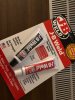
ok, I bought this it says it is good for metal and plastic.
I am going to prep knob number 1 now.
ok, I bought this it says it is good for metal and plastic.
I am going to prep knob number 1 now.
Last edited:
Your not epoxying it to the switch shaft..Just permanently epoxying the machined aluminum shell to the plastic core.Thats why it is imperative to glue it in the correct position.You only get one shot to get it right.this will fix the plastic piece to the knob so I will still be able to remove it if necessary?