• The move to the new server is done. There are some software and database maintenance updates in process. This has us passing the hat around to help out. We appreciate any donations. Seriously, even a dollar helps. The payment page may be found here - https://www.audiokarma.org/support.html

Yamaha CA-810 Relay Randomly Engages

:rflmao:
We all need a vacation … also I know of an exorcist who occasionally works on possessed amps … LOL
Don’t give up, it’ll be figured out …
@mbz ’s suggestion was an excellent one, I really thought this would be the end of it … we’ve definitely moved into the supernatural territory …
An exorcist we might need... yes
 
@AngelAT ,

Have you tried setting the speaker switch to off position and see if the relay trips or not? You might want to remove the speaker cables too for this.

What are the front panel settings? Can you set tone control, all filters, Rec out to Off position if they’re not currently?
Speakers are at off/phones;
Mode:stereo
Subs. and High filters: off
Bass and treble:0
Tone controls:defeat
Auto muting: 0db
Volume:0
Balance:center
Rec out: off
Input:Aux
Phono selector: 47lOhm
Loudness:flat
No speakers connected
Pre-main amp connectors: in place

And this is how I was doing the tests so far.
 
What happens if we pull TR601 and/or TR603? Both should be off under normal operation.
Suggest take your pick, remove one or both then leave amp on in background and wait for relay to cycle. No spkrs connected.
Pulled out TR601.
Relay engaged at the start.
Now waiting
 
...relay cycles again...
Good work.
My original thinking is that would leave D601,2 however I've seen an error in my thinking. TR606 Vb increases while TR604Vb decreases.
I was thinking the current flow through R604,5 under fault situation would set these voltages. Also I don't have a clear picture of what R611
is about. Need more thinking music.

Can you post a medium resolution pic of the solder/track side, need to include TR601,,,6 and the relay if possible. Need to verify the schematic.
 
@AngelAT ,Thank you for all the detailed info … I share your agony.

I’m wondering, would this relay trip if it were hard wired to be On all the time, bypassing the protect circuit. I don’t doubt the relay is good, just want to make sure where it’s sitting is physically fault-free.
Am not clear either what R611 is doing, limiting current inflow from Tr606c?
Unrelated: Does VR801 need to be readjusted (-25V rail?) if Xistors have changed? SM doesn’t say anything or at least I didn’t find any … maybe didn’t look hard enough.
 
When TR604 shuts down expect TR606 Vb to rise since no/low volt drop across R614 so Vb = Vc. Doubtful that it would go reverse bias as per my previous posts.
TR605 looks like AC detection.
Seems like TR601,2,3 turn off TR604 if offset detected.
Considered if this was due to an intermittent GND connection however would expect voltages to rise, ie, falling voltages suggests increased current flow/new current paths via transistors etc...
Nothing new in the above, just thinking out loud.

Don't see much point in lifting D601 or D602 or even C603.
I'd like to check the increase current flow theme, this could be done by monitoring the voltage drop across R604, ie, one probe connected to one side of R604 other probe connected to other side R604. Monitor voltage when both normal and relay cycling. Something of an act of desperation...
 
Don't see much point in lifting D601 or D602 or even C603.
Why not, at this point it couldn’t hurt … nothing could.

… Considered if this was due to an intermittent GND connection however …
Or an intermittent short? @AngelAT , can we remove the relay, completely clean any trace of solder, inspect the pads, and re-insert the relay? (I know you’re thinking :wtf:). In another thread today, just a hairline solder bridge was responsible for a lot of pain and burned resistors. Also, did you change the capacitors along with transistors? Just wondering.
 
Last edited:
Hello guys,
Thank you very much for the support!!!
I know this is also not easy for you.

I also replaced the capacitors.

Later today I will remove the relay, clean everything and reinsert it. Will also post pictures.
My plan is to reflow the whole protection circuit part of the board again.
 
Hello guys,
Thank you very much for the support!!!
I know this is also not easy for you.

I also replaced the capacitors.

Later today I will remove the relay, clean everything and reinsert it. Will also post pictures.
My plan is to reflow the whole protection circuit part of the board again.
Thanks for having confidence, this is one of the more baffling cases I’ve seen … but the amp is worth it …:D
Double-check the polarity of the caps too.
 
Thanks for having confidence, this is one of the more baffling cases I’ve seen … but the amp is worth it …:D
Double-check the polarity of the caps too.
Agree, very strange. I am thinking it might come up to be a stupid problem, but lets see..
I will have time to work later today.
As you say, the Yamaha is a good model and sounds really nice
 
Will wait on the pic of the trackwork to verify schematic.

Tempted to remove the smoothing cap C603 220uf, but reads like you've just replaced it. Also might cause some instability.
From Sparkplug updated schematic, appears most current through R604 and then onto D603 (not R605). Odd that TR605c is about
0V for both working and cycling cases.
 
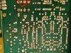
So, I resoldered most of the protection circuit.
This is how it looks:
IMG_20230222_230802.jpg

(Yes, the relay replacement is not to be proud of )
Please check - I always say that 4 eyes see better than 2.

Tr601 and Tr603 are back in place, also the resistor is connected.

Will check in DBT and then report.
 
Same story...
Relay cycling again - sometimes immediately after start, sometimes later.
BTW, when the amp is off the circled legs of the relay are shorted (the other channel not). I do not think this is normal. What might be causing this?
IMG_20230222_230802.jpeg
 
Will wait on the pic of the trackwork to verify schematic.

Tempted to remove the smoothing cap C603 220uf, but reads like you've just replaced it. Also might cause some instability.
From Sparkplug updated schematic, appears most current through R604 and then onto D603 (not R605). Odd that TR605c is about
0V for both working and cycling cases.
C603 was replaced with Nichicon FG. But this does not necessarily mean that it must be ok (tbh, so far never had problems with them, though).
Tr605c goes to 38.6V when amp in on to 0V when the relay engages and the other way around when the cycling begins.
 
The main board is screwed on the brass bars in the amp. There are some of these points that are earth (grounding) points. During all years these point, that are solder joints, oxidates and makes the boards grounding bad.
Also, the brass bars (sorry that I do not know what they are called in English) are also screw fitted into each other.
Have you removed the main board from the brass bars, resoldered all ground points, cleaned the brass bars from oxidation and refitted the main board again?
Hope you understand what I am writing. English is not my mother language.

I have come across CA-810 (as well as the other CA amps in this series as well as the CR series) where the grounding of the main board is poor and causes the speaker relay to go on and off. It is essential that the grounding points are clean.

I have never thru all my years repairing Yamaha receivers had the need to replace the speaker relay.
Excellent input, the much needed voice of ‘direct experience’, makes perfect sense. I have very little doubt the problem is of physical (connection, corrosion, etc.) nature, but, speaking for myself here, not having hands on experience with CA or CR series Yamaha amps, I would have never guessed the issues with the grounding points and the brass mounting bar. Hopefully this will turn out to be the culprit and fix the problem, I say hopefully because we’ve been here before
BTW, there’s nothing wrong with your English … :trebon:
 
Tr605c goes to 38.6V when amp in on to 0V when the relay engages and the other way around when the cycling begins.
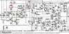
Here’s the latest schematic reflecting this, didn’t have this info before. Also what is the voltage during failure at the circled point? I’d expect it to be very close to that of Tr601c …
E3B198A6-2636-4863-98BF-B32E2CF97667.jpeg
 
I did give grounding some thought however dismissed it since I still favour a scenario involving increased current flow. That said, certainly check GND connections.
Will look at the trackwork.
 
Back
Top Bottom