


Sparkplug
Super Member
Yes, I have to agree, @AngelAT has done a fantastic job, most people would have given up, mind you, the CA-810 is worth saving.
Time for some more brainstorming,
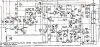
TR605 Vb increases since TR604 has shut down so low TR605 Ib and volt drop at R613.
Same with TR606b, ie, TR604 shuts down so low current through TR605Ic, D603, R604.
TR605 and TR604 provide a current path to GND that needs to be open for TR606 to correctly bias.
When a real dc offset occurs additional Ic through TR601 or TR603 causes higher volt drop through R605
setting TR604b to 180mV?
Possible minor error in schematic, would expect TR601e and TR602e to be connected to GND, ie, missing "dot"
I have some questions after reading your last post, another very plausible explanation.
Why would a shut off Tr604 raise the voltage of Tr605b? When Tr604 shuts off, its collector correct drops to near zero, that current is also the emitter current of Tr605 and the collector current of Tr605, all dropping to near zero, i.e. I-tr604c ≈ I-Tr605e ≈ I-tr605c. Base currents of both Tr604 and Tr605 are very small and negligible (μA range). The collector current of Tr605 is provided directly from the +36V rail through R614, when it drops to zero, the current through R614 decreases and Tr606b voltage increases. This is reflected in the collected data.
Tr605b voltage is determined by a simple voltage divider comprised of R612 and R613, setup on that rectified unsmoothed supply line from the bridge diode. The output of the bridge diode prior to smoothing is around 29.5V (easy to calculate). Calculating the base voltage of Tr605, we get ≈ 3.7V. V-tr605b = (29.5 x R612) / (R612 + R613) ≈ 3.7V
Why would this voltage change at all? C604 is, I think for some degree of smoothing?
Edit: I think I’ve answered my own question, the base impedance of Tr605 is of course different in On and Off states, changing the eq. resistance seen at the base by the current coming through R613 and hence different voltages measured.
None of this explains where the whole thing gets triggered though, I’m looking at a couple of other things too, we’ll see …
@AngelAT , as if you hadn’t done enough, could you monitor the main supplies (+25V, +39V, etc.) during the relay fault? Do they stay constant? Thanks and apologies for so many questions.
Last edited:




 … edited my post, less to do …