• The move to the new server is done. There are some software and database maintenance updates in process. This has us passing the hat around to help out. We appreciate any donations. Seriously, even a dollar helps. The payment page may be found here - https://www.audiokarma.org/support.html

Yamaha CA-810 Relay Randomly Engages

Yeah, apologies from me, it was not a great explaination.

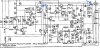
We are trying to work out why the relay randomly releases. One possible cause is a spike in dc voltage. If you look at the sm and dc offset adjustment they ask you to check for 0V at Ro and Lo. Looking at the schematic, you will see that Ro and Lo are after the relay, so all good if the relay is engauged. But if the relay randomly releases then Ro and Lo are no longer connected to the power amps. So working back from the relay you will see a connection at the emitter resistors. So monitor the voltage to GND at this point, xxmV is not unreasonable, looking for a drift or spike into the hundreds of mV. If you are able to "provoke" the fault then that would speed things up.
OK, I understand. Thank you!
Will measure and come back
 
Last edited:
So, as I see it, there is no spike in either channel before the relay starts engaging:


I just wonder why such a big difference in the two channels when measured to ground. Could it be that the em. resistors are giving me trouble?
Clicking starts some 30-40 mins after turn on. Sometimes it takes an hour. It is also strange how it switches off - just for a second or two and then turns on again.
 
Last edited:
  • Like
Reactions: mbz
So, as I see it, there is no spike in either channel before the relay starts engaging:
Great, voltages were stable while the relay was cycling on-off, time to look elsewhere, maybe power supply to the relay, will dig up some test points.


I just wonder why such a big difference in the two channels when measured to ground. Could it be that the em. resistors are giving me trouble?
emitter resistors are probably ok, would expect the voltages at emitter resistors to bounce a little if they were becomming intermittent.
Difference may be due to which end of the emitter resistor you are measuring, ie at transistor emitter or node/junction with other resistor.
 
Try to monitor voltage at TR606base, you can do this at R614 or R610 which both connect to the base. sm shows +40.5Vdc, again looking for a stable voltage. Maybe one of the controlling transistors (TR605,4,,,) is dropping out because of intermittent power.
 
At the base of TR606 we have 37.5V and when the relay cuts the voltage goes to 38.6V
I replaced all transistors at the protection circuit. For TR606 I used KSA1015
 
What puzzles me is that one end of the R469 I have 20mV and the other end (where the connection to R471 is) I have 5mV. At the right channel both sides I have 20mV
 
What puzzles me is that one end of the R469 I have 20mV and the other end (where the connection to R471 is) I have 5mV. At the right channel both sides I have 20mV
At least based on the SM, the voltage difference between the two ends of R469 (emitter side - R471 side) and those of R470 is the idle current setting which should be set at 20mV ±5mV. The other channel (R) should reflect that too (right now it’s indicating zero volts based on your measurement above). Also the SM refers to CP3 on the L channel where on the schematic, it seems to be on the R channel, possibly an schematic error. Maybe you could try to readjust the idle current setting for both channels.
76B53C59-6470-46E2-AE9E-2462DEC37753.jpeg
 
Last edited:
At the base of TR606 we have 37.5V and when the relay cuts the voltage goes to 38.6V
TR606 is no longer correctly biased so relay releases. In turn monitor at TR605b, TR604b. A stable voltage is good. Probably TR604. Hopefully
someone can correct me...
 
A question, if Tr606 is incorrectly biased, which may very well be, why does it take an hour for the relay to cut? :dunno:, why not right away?

Also, what is the voltage reading at the points marked below? Noticed somehow +36V is becoming +41.3V by the time it gets to the emitter of Tr606, it may be an error but is confusing … am I reading this correctly? Trying to check Tr606 bias condition, hence the question.
6A23A657-E963-4CEC-BE09-C4B305A51CFA.jpeg
 
Now I am a bit confused by what I measure...

I measure the following:
Both ends R469 19.8 mV
GND and Emitter end of R469 25.2 mV
GND and Link w. R471 5.3 mV

Both ends R470 17.6 mV
GND and Emitter end of R470 41.7 mV
GND and Link w. R472 24.1 mV

If I understood the Sm, I thought I should measure both ends of the em. resistors.

I re-read this post, the results are not confusing. The common point between R469/R471 and R470/R472 are not ground. Your measurements make sense:
Voltage across R469 = Voltage @ emitter wrt G - Voltage @ link w/R471 wrt G

25.2mV - 5.3mV = 19.9mV ≈ 19.8 mV (your reading on the L channel, voltage across R469, in spec)
41.7mV - 24.1 mV = 17.6 mV —> (your reading on the R channel, in spec)

This may or may not solve your problem but at least you can doublecheck the voltages you’ve set and readjust if necessary. Best to follow the SM instructions.
 
Last edited:
A question, if Tr606 is incorrectly biased, which may very well be, why does it take an hour for the relay to cut?

Yeah, I wanted to brainstorm that idea...

TR606e is fed from rectifiers D807,9. Ballpark it's fixed at 38.2Vdc (TR606b is 37.5V, post #45).
If "the fault" causes TR606b to raise above Ve 38.2V (eg, 38.6V, post #45) then TR606 becomes incorrectly biased.
Possible candidates are no current flow through TR604,5 so no volt drop across R609,610, 614. Suggest monitor
the base of these TR's to see if someone is telling one (TR604) to switch off or track damage results in same.

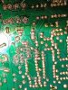
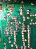
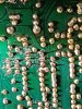
If possible, post a hi-re pic of trackwork that includes TR601,4,5,6.
 
Last night I did readjust the bias. All looks ok with it. Also checked the emitter transistor and it is right on spec (as you already suggested).
Will monitor the other TRs at the protection circuit and will report.
 
Yeah, I wanted to brainstorm that idea...

TR606e is fed from rectifiers D807,9. Ballpark it's fixed at 38.2Vdc (TR606b is 37.5V, post #45).
If "the fault" causes TR606b to raise above Ve 38.2V (eg, 38.6V, post #45) then TR606 becomes incorrectly biased.
Possible candidates are no current flow through TR604,5 so no volt drop across R609,610, 614. Suggest monitor
the base of these TR's to see if someone is telling one (TR604) to switch off or track damage results in same.

If possible, post a hi-re pic of trackwork that includes TR601,4,5,6.
Certainly one explanation, can’t say for sure … need to look at it some more.
 
The measurement is as follows (base):
Tr606 38.6v to 37.3v when relay engages
Tr605 3.45v to 0.8v
Tr604 0.4v to 0.7v
Tr601 11.5mV stable

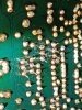
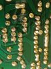
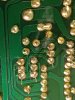
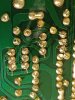
And some pictures of the area:
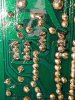
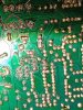
IMG_20230215_223101.jpg IMG_20230215_223109.jpg IMG_20230215_223213.jpg IMG_20230215_223156.jpg IMG_20230215_223101.jpg
 
  • Like
Reactions: mbz
The measurement is as follows (base):
Tr606 38.6v to 37.3v when relay engages
Tr605 3.45v to 0.8v
Tr604 0.4v to 0.7v
Tr601 11.5mV stable
Just to confirm, the first voltages(38.6, 3.45. 0.4) were taken after the relay randomly released, not voltages taken during the first 4-5 seconds after power on (ie, the mute period)?

Not completely definitive but TR604 is not fully conducting, D602 replaced? maybe TR603? I will look at the trackword around TR604b
 
Take a look at the solder fleck on TR601(?) I can see a gap but maybe when things heat up or air currents...
CA810_TR601.jpg

Appears to be between TR601 c-e which would cause increased current through R605 and a dip in TR604b voltage.
 
Last edited:
Take a look at the solder fleck on TR601(?) I can see a gap but maybe when things heat up or air currents...
View attachment 2800392
The solder work on this board needs a total clean up.
If the general voltages given on the schematic are representative of those during normal operation (relay closed), then the measured ones here are pretty much in agreement. The base of Tr606 maybe a tad low? Still can’t see why the relay would open in the first place …
 
Back
Top Bottom