• The move to the new server is done. There are some software and database maintenance updates in process. This has us passing the hat around to help out. We appreciate any donations. Seriously, even a dollar helps. The payment page may be found here - https://www.audiokarma.org/support.html

Yamaha CR-1020 Receiver Restore and Facelift

What approach should I take for the transistors ?

  • 2. test all resistors and only change the bad ones

    Votes: 0 0.0%
  • 3. test only the trouble maker transistors and change only those that are bad

    Votes: 0 0.0%

  • Total voters
    12
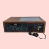
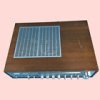
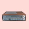
I've been a member for a few years now. I have read and learned a lot as a result. Now I want to share one of my projects. I bought this receiver from the Bay about three months ago and last week it stopped powering on. I diagnosed this as a switch fault but I had planned on doing a recap and restoration, so now is the time. Other than bulbs being out and the power meter clearly being out of adjustment (very low) the receiver works well and sounds good to me. The face is very clean but the cabinet has some nicks and scratches. As such, I also will be re-veneering it with an ebony macassar veneer (blonde and black stripped). Sorry, as usual I forgot to take any before pictures and I already have the cabinet off. Here are the Ebay pictures and I will post better pictures as I go. My research on this site and others suggests that these transistors are prone to issues: 2sc1213A, 2sc1918, 2sc458, and 2SA844. This is my first transistor project so here is question for you.
 

Attachments

  • s-l1401.jpg
    s-l1401.jpg
    3.1 KB · Views: 38
  • s-l1403.jpg
    s-l1403.jpg
    3.6 KB · Views: 38
  • s-l1406.jpg
    s-l1406.jpg
    4.6 KB · Views: 38
Register to hide this ad
. I bought this receiver from the Bay about three months ago and last week it stopped powering on.
I usually advise all buyers of the antique equipment who do not know its history not to turn it on at all without undergoing restoration. Any device over 40 years old needs it. Also, people often sell equipment when problems start and they don’t want to spend money on fixing them. It is also common to see signs of poor previous repairs. A lot depends on the condition of the particular device and its damage. Sometimes it can be very expensive and time-consuming to restore after unskilled repairs. A good example is in this video.
 
build a dim bulb tester before you do anything else. it may just save you if you happen to put a transistor or capacitor in wrong.

testing transistors is good practice but 3 recent units on my bench (2 sansuis and a quadraflex) all had bad transistors that tested fine in the little testers.

definately shotgun the troublemaker transistors.
 
I am finally into this restoration and I have a question. I am working on the power supply section and transistor TR702 (2SB544 - Sanyo "low frequency power amp electronic governor") has a 477 ohm resistor soldered on the bottom of the PCB from the base to the emitter. This resistor is not on the schematic and appears to not be factory installed either. I tested the transistor with my cheapo tester and it tests good (hfe 120 per spec). Someone put it there for a reason (good or bad) but it is not the way it was built. I checked for a service bulletin or the like describing this mod but found nothing. Also, I am following along with a Trevor's Bench youtube video on this restoration and he doesn't mention it . Should I remove the resistor or leave it? My inclination is to remove it. Does anybody have any insight on this? (
)
 
Last edited:
I am finally into this restoration and I have a question. I am working on the power supply section and transistor TR702 (2SB544 - Sanyo "low frequency power amp electronic governor") has a 477 ohm resistor soldered on the bottom of the PCB from the base to the emitter. This resistor is not on the schematic and appears to not be factory installed either. I tested the transistor with my cheapo tester and it tests good (hfe 120 per spec). Someone put it there for a reason (good or bad) but it is not the way it was built. I checked for a service bulletin or the like describing this mod but found nothing. Also, I am following along with a Trevor's Bench youtube video on this restoration and he doesn't mention it . Should I remove the resistor or leave it? My inclination is to remove it. Does anybody have any insight on this? (
)
Leave it. Always, always leave factory mods.
 
Leave it. Always, always leave factory mods.
It doesn't appear to be a factory fix (flux was left on the PCB which now looks burnt); however, this transistor is on the speaker relay coil supply circuit which is definitely functioning properly; so factory or not leaving it does make sense. So for my understanding, this is a NPN so this resistor is lowering the voltage on the emitter and increasing the base to emitter voltage, correct? If so, does this make the transistor more sensitive to changes in the circuit?
 
Last edited:
It doesn't appear to be a factory fix (flux was left on the PCB which now looks burnt); however, this transistor is on the speaker relay coil supply circuit which is definitely functioning properly; so factory or not leaving it does make sense. So for my understanding, this is a NPN so this resistor is lowering the voltage on the emitter and increasing the base to emitter voltage, correct? If so, does this make the transistor more sensitive to changes in the circuit?
It could be a hack to get the unit out of protection instead of fixing it properly. The flux could also be from a factory hand solder. Once you get done you could always replace it if needed. Definitely replace that transistor.
 
It doesn't appear to be a factory fix (flux was left on the PCB which now looks burnt); however, this transistor is on the speaker relay coil supply circuit which is definitely functioning properly; so factory or not leaving it does make sense. So for my understanding, this is a NPN so this resistor is lowering the voltage on the emitter and increasing the base to emitter voltage, correct? If so, does this make the transistor more sensitive to changes in the circuit?
If not factory, then never mind. Sorry - wasn't clear.
 
It could be a hack to get the unit out of protection instead of fixing it properly. The flux could also be from a factory hand solder. Once you get done you could always replace it if needed. Definitely replace that transistor.
Now that makes sense to me. I am going through the power supply first, then I plan re-assemble it just enough to safely power it up before moving on to the other boards. Re-accessing the power supply board will be easy if needed. Thanks
 
First, I want to re-state this is my first transistor unit restore - I have some experience with old tube gear. I have finished refreshing the power supply boards. I did not re-install the resistor @jefferyhenr helped me with. I replaced all the capacitors and several of the transistors that are on different "naughty" lists I found on AK and other sources. I also changed the power transistors that are know to get hot with an equivalent power transistors with 2x higher dissipation rating. After I finished soldering but before I brought it up, I checked my resources; one source that I found latenight (not on AK) suggested that the 2SC1918 fail frequently and KSC1845s are a good replacement; I couldn't find that source again. However, I already changed the 12 c1918 that are in this section. I debated whether to just change them back or to proceed. I did a little research and the 1845s are much more robust, but are they a good replacement? I have no idea. I have a dim bulb setup so I brought it up anyway. At first it was going into protect with even modest volume so I checked all the voltages on the transistors; I had low voltages on the transistors in the NB supply circuit, which lead me to a AC supply wire I snapped off while changing parts. After fixing that, I rechecked my voltages and everything seems to be in spec. I can set it to full power into an 8 ohm load without it going into protection. The transistor voltages are not exactly per the schematic but are pretty close; in a tube amp I know this would be ok but for transitors? I attached my voltage checking chart that includes the spec'd V and the measured V; does anyone see anything that looks suspect? Is there anything else I should test before moving on to the mains? Thanks for any and all replies.

FYI - The transitors I changed are as follows: OLD>NEW, 2SA673 > KA1013YBU, 2SA844>KSA1015YTA, 2SC1918>KSC1845, 2SC458B-C>KSC1845, 2SD234>MJE15030G
 

Attachments

Last edited:
I stuck;

I am done with the recap and replacement of trouble transistors and I also replaced the lamps with 9-12v LEDS. Bias is set. The DC offset measures about 5mV on both channels. I can drive the power up without going into protection and I don't get any clipping until I get above 26.5 volts (87 watts); the sine wave looks clean on both channels. I connected the receiver to test speakers and a cd player and it sounds quite good. However, the receiver went into protection after playing for about 10 minutes. I reset it by turning the power off and on but about 10 minutes later it did it again. Nothing was hot to the touch but the right power meter was working intermittently. I also noted the tuner works but the signal meter doesn't; both power meters go to zero when i touch the tuner knob or switch to signal meter manually. So I disconnected the receiver and put it back on the bench with the DBT and inspected the power meter circuit. I discovered by touching the adjustment trimmer pot for the right meter it would work (I assume it has bad solder joints). I haven't taken it apart to fix the trimmer yet, but I'm still having trouble with going into protection. I checked the power supply voltages and I'm getting 47.5+/- on the amps and 27.1+/- to the tuner and pre-amp. It doesn't matter if I'm running 1 watt, 20 watts, or 80 watts, about every 10 minutes it goes into protection. What should I check first to fix the protection issue?
 
Last edited:
It doesn't matter if I'm running 1 watt, 20 watts, or 80 watts, about every 10 minutes it goes into protection. What should I check first to fix the protection issue?
The common scenarios for protection are,
i) DC spike on one power amp channel, so protection circuit kicks in
ii) failure in the protection circuit, eg, relay drop out
iii) power supply failure that feeds protect(more so) and/or power amp circuits

Does protection still kick in when no audio playing?
Start by monitoring the voltage at the power amp out pins, brown and yellow wires. Looking for stability (5mV) or does it race/dance(5-100mV??) about, no audio playing.

Monitor the relay coil voltage, ie, at D719 cathode, again looking for stability, you can play audio to provoke the fault.
 
Does protection still kick in when no audio playing?
Start by monitoring the voltage at the power amp out pins, brown and yellow wires. Looking for stability (5mV) or does it race/dance(5-100mV??) about, no audio playing.

Monitor the relay coil voltage, ie, at D719 cathode, again looking for stability, you can play audio to provoke the fault.
mbz - Thanks for the advise: I have stability on the power amps and relay coil. I played the radio for 30-40 minutes to get it to fail while I was monitoring the coil but it didn't fail; I even switched it to a resistive load so I could drive the amplifiers and it still didn't fail. So, I reconnected the receiver to my test system in the garage and it's been playing the radio and CD player for about 5 hours and has not gone into protection. A real head scratcher. Not usually the case but it seems to have fixed itself. I'm going to let it keep playing overnight and see what I get. If it doesn't fail overnight, tomorrow I am going to fix the solder joints on the meter pot and I will double check the PS boards for bad solder joints. I also have a connection issue with the selector switch that De-oxit didn't help so I am going to remove the preamp board so I can open up the switch and clean it properly. I have to admit that I don't have the same luck with de-oxit that most people do; at least 75% of the time I end up needing to remove, disassemble, clean and re-install troublesome pots and switches.
 
Sounds like a good plan, intermittent issues are a pita, try to work out how to provoke the issue.

I have to admit that I don't have the same luck with de-oxit that most people do; at least 75% of the time I end up needing to remove, disassemble, clean and re-install troublesome pots and switches.
Those toggle switches have a plastic hood that encases the switch mechanism, the hood prevents deoxit from reaching the switch contacts so most of that 75% are wasting their time. If you are sure the switch is intermittent then it needs to be stripped down/cleaned.
 
I pulled the selector toggle switch and volume/balance pot (yes absolute PITA) and also re-flowed the solder on the meter trimers and I have a completely functioning receiver. I haven't been able to provoke a protection failure and the unit has been powered up and playing music for 20+ hours over the WE. The only issue I have now is a moderate pop when I power down the unit; it is not related to volume (IE the same pop with volume at 0 as with it up). I expect this is an issue with the relay so I am going to try cleaning the contacts; does that sound right?
 
I have now is a moderate pop when I power down the unit; it is not related to volume (IE the same pop with volume at 0 as with it up). I expect this is an issue with the relay so I am going to try cleaning the contacts; does that sound right?
The pop is probably caused by the relay not releasing quick enough (so power off transients are output to spkrs). Maybe relay contacts but I'd be thinking more on relay control TR702,6 and C738. Assume you have not increased the value of C738.
 
The pop is probably caused by the relay not releasing quick enough (so power off transients are output to spkrs). Maybe relay contacts but I'd be thinking more on relay control TR702,6 and C738. Assume you have not increased the value of C738.
Thanks again for the input. For c238 I put a 47uf/50v in place of the 47/16 that was there; i don't think that would cause a problem. Note then I started on this it had a 470ohm resistor across the base and emitter of TR702 which did not appear to be factory that I removed (see posts #5-10). I checked the voltages on TR702 and 6 they were close to the schematic (I was pressed for time and didn't have paper and pencil so I didn't record them).
Burnt out lamps or
miss wired lamps.

Thanks for the input. This service included replacing the bulbs with these LEDs:

30pcs 12 Volt 5mm White LED Lights Emitting Diodes Pre Wired 7.9 inch DC 12v LED Light Clear Lens Small LED Lamps​


However, I didn't change the bulb resistors: R738 (100ohm) or R739 (180ohm). These LEDs draw 20mA each. I just did a direct replacement so the meter LEDs are 2 sets of 2 parallel LEDs in series, just like the bulbs were. I'm getting 19.8vdc on LB, about 9.9vdc on LC, and 9.8vdc on DL. All 5 are working normally. Do I need to change the values on R738 and/or R739?
 
Last edited:
Thanks for the input. This service included replacing the bulbs with these LEDs:

30pcs 12 Volt 5mm White LED Lights Emitting Diodes Pre Wired 7.9 inch DC 12v LED Light Clear Lens Small LED Lamps​

Amazon.com
However, I didn't change the bulb resistors: R738 (100ohm) or R739 (180ohm). These LEDs draw 20mA each. I just did a direct replacement so the meter LEDs are 2 sets of 2 parallel LEDs in series, just like the bulbs were. I'm getting 19.8vdc on LB, about 9.9vdc on LC, and 9.8vdc on DL. All 5 are working normally. Do I need to change the values on R738 and/or R739?
Snap a photo of the wire wrapped pins( LB ,LC & DL on the PS/relay circuit board.
 
Back
Top Bottom