• The move to the new server is done. There are some software and database maintenance updates in process. This has us passing the hat around to help out. We appreciate any donations. Seriously, even a dollar helps. The payment page may be found here - https://www.audiokarma.org/support.html

Yamaha CR-1020 Receiver Restore and Facelift

What approach should I take for the transistors ?

  • 2. test all resistors and only change the bad ones

    Votes: 0 0.0%
  • 3. test only the trouble maker transistors and change only those that are bad

    Votes: 0 0.0%

  • Total voters
    12
Snap a photo of the wire wrapped pins( LB ,LC & DL on the PS/relay circuit board.
I see where you are coming from but when I installed the LEDs I just nipped the wires at the bulbs and soldered/shrink tubed the LED wires to the existing circuit wires; white to red and black to white (LED to existing circuit, respectively). I didn't re-wire it. It is definitely still wired like the schematic and all of the LEDs work so I assumed the polarity is correct. I rechecked the voltages and LB to LC is 9.9, LC to E is 9.9 but DL to E is actually 15.7. I used test leads to connected an old bulb in parallel to the LED on the DL circuit and the voltage came down to 9.2 and the pop was dramatically reduced but still present. (I plan to change the 180ohn R739 with a 500 ohm resistor to see if that gets me to 9 - 12v). I then cleaned the contacts on the relay, which had no real effect but I did notice with the power off (unpluuged), when I was cleaning the contacts every time I broke and remade the contact I got the pop and it continued for several cycles. Is this normal? Based on the fact that the adding the bulb to the DL circuit reduced the pop should I be looking into adding some load to the LB circuit? Perhaps these are the wrong LEDs to use and I should using lower voltage LEDs with a line resistor?

Maybe relay contacts but I'd be thinking more on relay control TR702,6 and C738
The voltages on TR702 are b=11.62, c=12.20, and e=12.25; TR706 are b=0.65, c=0.12, and e=0.005
 
Last edited:
when I was cleaning the contacts every time I broke and remade the ground contact I got the pop and it contuinued for several cycles. Is this normal?
No. It is not suppose to pop at all.

Capacitor discharging is causing the progressive declining pops.

I don't fart around with cleaning relay contacts. I replace them with new relays.
 
Last edited:
New relay on order. Also, I ordered some old fashion 12v grain of wheat bulbs to eliminate the LEDs as an issue if the relay doesn't correct the pop. This has been a fun project and a good learning experience but after having this thing apart for a couple of months I won't be sad to get this off my bench.
 
Parts came in yesterday. First I replaced the relay, which had no affect on the poping issue. Then I replaced the LEDs with grain-of-wheat bulbs and the popping issue is gone. (Hooray). Maybe someone can explain why 12v LEDs are different in this circuit than 12v bulbs, but this receiver is going to have bulbs (I like the look better anyway).

Over the WE I re-veneered the cabinet so hopefully I will get a chance to finish putting my CR-1020 together today. Pictures and a recap of the restoration to follow...
 
After two months on the bench, I am done with the restoration. Thanks to all who helped me through this project.

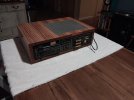
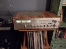
For the restoration first I fixed the failed power switch by disassembling it and flipping the burnt contact rocker; I also switched the rockers so the half burnt rocker switches the outlet and good rocker switches the receiver power. Then I replaced 100+ capacitors, 5 fuse/resistors, the speaker binding posts, and the panel light bulbs with LEDs. I also replaced 50+ high failure transistors including the TR712/715 (2sd234s which overheat) with MJE15030Gs because they have twice the power dissipation rating; in addition to replacing them, I installed some extruded aluminum finned heat sinks in lieu of the stock heat sinks. For the amplifiers, I also re-applied thermal paste on the main transistors and replaced the trim pots with 10-turn trim pots, which made biasing much easier and more accurate. I swapped out the binding posts with pre-assembled 5-way posts I got from speaker-terminal.com; they fit perfectly and were super easy to install. When I finished, it was popping when powering down so I replaced the relay (didn't fix it) and switched out the LEDs with new bulbs (fixed it).

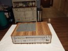
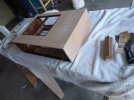
For the face lift, I stripped the old veneer off the cabinet and replaced it with zebra wood veneer. I used Heat Lock iron-on veneer glue and it worked very nicely. I finished the cabinet with 4 coats of spray-can oil-based Varathane sanding with 320 between coats.

I haven't listened to this reciever for 4 months+ (power switch failed) so it's hard to assess the improvement but it sure sounds sweet; definitely has that clean, pure, and honest Yamaha sound . Oh, and now all the meters work like they should.
 

Attachments

  • 20240904_195555.jpg
    20240904_195555.jpg
    100.3 KB · Views: 34
  • 20240904_195756.jpg
    20240904_195756.jpg
    103.7 KB · Views: 33
  • 20240904_200154.jpg
    20240904_200154.jpg
    114.8 KB · Views: 35
  • 20240904_200204.jpg
    20240904_200204.jpg
    99.1 KB · Views: 31
  • 20240831_154539.jpg
    20240831_154539.jpg
    126.7 KB · Views: 32
  • 20240904_214835.jpg
    20240904_214835.jpg
    92.4 KB · Views: 33
Last edited:
Interesting veneer!

I have the same unit with several large dents. Going to have to go wood filler and re-veneer - was there any trouble getting the old veneer off? I see a scraper - did you use any heat/humidity?
 
Interesting veneer!
Yes, It's real wood (composite anyways) but it does have kind of a 70s shag carpet-lava lamp look. I didn't want to go with a typical mahogany or walnut so... success! It's growing on me but I don't think I'd use zebra wood again.

was there any trouble getting the old veneer off? I see a scraper - did you use any heat/humidity?
I saw online people were using a wet cloth and an iron with steam, which was plan B but I wanted to avoid adding a bunch of moisture so I wouldn't have to wait to start on the veneering. I used a heat gun and putty knife and peeled it off in 1/2" to1" strips. It was pretty easy and only took about 40 minutes to do the whole thing.
 
Back
Top Bottom