• The move to the new server is done. There are some software and database maintenance updates in process. This has us passing the hat around to help out. We appreciate any donations. Seriously, even a dollar helps. The payment page may be found here - https://www.audiokarma.org/support.html

Yamaha CR-1040 Maintenance

Most probable cause of this is a failed output "power pack", Yamaha IG02960 or Sanyo STK0080II. You could remove it and verify that the receiver will then come out of protection, but going further than that goes beyond the realm of simplicity.
Is the TP1 reading conclusive, leaving no need for further diagnosis? If so, I will have to reluctantly begin the search for a working 1040 (or 840?,) to harvest the chips.

The unit, other than the dim meter bulbs, has always worked without issue, while ignoring the cleaning of inputs. The only thing out of the ordinary in its history took place after our move. I had the bright idea to use a power conditioner (it had also been in storage) upon start up, given I didn't know the condition of the new house electrical. It is an action I obviously regret in hindsight, but testing of the conditioner and the suspect outlet later showed nothing out of the ordinary. However, I continue to blame the conditioner, though it is most likely coincidental.

Assuming I find a working parts unit, shouldn't I be wary of what caused the failure? The expense of working parts units somewhat limits random parts swapping. Would a startup power surge ignore everything else in the receiver and just take out the chip? There was no smoke, sparks or popping of any kind, just a quiet protection light.

I sincerely appreciate your comments.

Bob
 
Very doubtful it was the power conditioner that caused the problem, so I think that was just a coincidence. More likely it was just that the unit sat unpowered for a while and when powered up again, the aging caps maybe let a bit of DC through, took too long to reform, etc. Could have been just moving the unit around during the move, flexed the chassis just enough to crack or weaken solder joints, loose a ground, what have you. Who knows for sure? What I do know is that parts fail, especially after many decades of use, and it is unrealistic to expect any unit of that age to be completely trouble free. It is the main reason for recapping, since these are some of the parts known to degrade with age. Recapping is an insurance policy against further failure down the road, but it is not a guarantee. NOTHING is guaranteed! Even after a full recap, maybe even swapping out other devices like transistors, diodes and other parts, there are still plenty of old components left. Doing all of that preventive work usually buys you more time and peace of mind but again, nothing is guaranteed.

And I am in the same boat. I have a mint condition CR-840 I bought locally years ago. Powers on, but no click, stays in protection. Since it is a CRx40 series and I've had several of these series of receivers before, I'm pretty sure it is a faulty power pack or pre-driver chip, but have not the time to dig into it and get it repaired. So it sits in the waiting pile. One day I will probably seek out a CR-2040, since it uses discrete output devices, unlike the rest of the x40 series. Until then, my CR-2020 and C-60/M-4/T-80 combo will do just fine.
 
Very doubtful it was the power conditioner that caused the problem, so I think that was just a coincidence. More likely it was just that the unit sat unpowered for a while and when powered up again, the aging caps maybe let a bit of DC through, took too long to reform, etc. Could have been just moving the unit around during the move, flexed the chassis just enough to crack or weaken solder joints, loose a ground, what have you. Who knows for sure? What I do know is that parts fail, especially after many decades of use, and it is unrealistic to expect any unit of that age to be completely trouble free. It is the main reason for recapping, since these are some of the parts known to degrade with age. Recapping is an insurance policy against further failure down the road, but it is not a guarantee. NOTHING is guaranteed! Even after a full recap, maybe even swapping out other devices like transistors, diodes and other parts, there are still plenty of old components left. Doing all of that preventive work usually buys you more time and peace of mind but again, nothing is guaranteed.

And I am in the same boat. I have a mint condition CR-840 I bought locally years ago. Powers on, but no click, stays in protection. Since it is a CRx40 series and I've had several of these series of receivers before, I'm pretty sure it is a faulty power pack or pre-driver chip, but have not the time to dig into it and get it repaired. So it sits in the waiting pile. One day I will probably seek out a CR-2040, since it uses discrete output devices, unlike the rest of the x40 series. Until then, my CR-2020 and C-60/M-4/T-80 combo will do just fine.
I own a Variac and dim bulb tester, but for whatever reason did not feel the need to use them. My unit is cosmetically mint on the exterior, with the internal appearance being better than 90 percent of what I see online. Of course, I will want to recap and deep clean the guts at some point, given its sentimental value, but for now I just need to find a donor unit. I noticed there are chips for sale on online market places, but a quick read of the sellers' feedback should change anyone's mind as to the authenticity of the part. In the meantime, the CR-420, though old and tired, can push the L-36's without any issue. However, it will not push the new speakers (LRS Plus) I have been considering, hence the need for the 1040.
 
Is the TP1 reading conclusive

Not 100%, I'm afraid. It might (or might not) be revealing to measure the voltage on certain pins of the power pack. If everything else was intact, I'd expect pins 3 and 8 to bear the same voltage as TP1, and I'd expect pins 1 and 0 to be strongly negative, like negative 40-odd volts.

Some extra notes:
  • Power pack pin 0 is what you would expect to be designated "10".
  • If pins 3 and 8 are not the same voltage, then at least one emitter resistor has failed as a result of the power pack failing. These resistors are the large white 0.47 ohm parts near the power pack. If either has failed, both should be replaced. This condition, if it exists, would have been stressful for the predriver, but it's pretty much a matter of luck whether it will have actually damaged it.

Assuming I find a working parts unit, shouldn't I be wary of what caused the failure?

Sometimes power output devices suffer from what, as far as I can tell, are spontaneous failures. About the only other component that could result in a power pack failure is the predriver, and the predriver would have to have failed in a specific and unusual way. I don't think I've ever seen that, myself.

Hope you have luck finding replacement parts. Don't use a CR-840 power pack - it would probably seem to work just fine, for a while, and then fail under load.
 
Not 100%, I'm afraid. It might (or might not) be revealing to measure the voltage on certain pins of the power pack. If everything else was intact, I'd expect pins 3 and 8 to bear the same voltage as TP1, and I'd expect pins 1 and 0 to be strongly negative, like negative 40-odd volts.

Some extra notes:
  • Power pack pin 0 is what you would expect to be designated "10".
  • If pins 3 and 8 are not the same voltage, then at least one emitter resistor has failed as a result of the power pack failing. These resistors are the large white 0.47 ohm parts near the power pack. If either has failed, both should be replaced. This condition, if it exists, would have been stressful for the predriver, but it's pretty much a matter of luck whether it will have actually damaged it.


Sometimes power output devices suffer from what, as far as I can tell, are spontaneous failures. About the only other component that could result in a power pack failure is the predriver, and the predriver would have to have failed in a specific and unusual way. I don't think I've ever seen that, myself.

Hope you have luck finding replacement parts. Don't use a CR-840 power pack - it would probably seem to work just fine, for a while, and then fail under load.
Thank you for sharing your knowledge and taking the time to guide me in what I know is the right direction. As soon as I have done a little homework, and taken those additional voltage readings, I will report back.

Bob
 
Not 100%, I'm afraid. It might (or might not) be revealing to measure the voltage on certain pins of the power pack. If everything else was intact, I'd expect pins 3 and 8 to bear the same voltage as TP1, and I'd expect pins 1 and 0 to be strongly negative, like negative 40-odd volts.

Some extra notes:
  • Power pack pin 0 is what you would expect to be designated "10".
  • If pins 3 and 8 are not the same voltage, then at least one emitter resistor has failed as a result of the power pack failing. These resistors are the large white 0.47 ohm parts near the power pack. If either has failed, both should be replaced. This condition, if it exists, would have been stressful for the predriver, but it's pretty much a matter of luck whether it will have actually damaged it.


Sometimes power output devices suffer from what, as far as I can tell, are spontaneous failures. About the only other component that could result in a power pack failure is the predriver, and the predriver would have to have failed in a specific and unusual way. I don't think I've ever seen that, myself.

Hope you have luck finding replacement parts. Don't use a CR-840 power pack - it would probably seem to work just fine, for a while, and then fail under load.
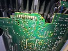
I finally had a moment to remove the bottom plate and take a look at the ?power pack? closest to the front of the receiver, and I'm assuming it's the one associated with TP1. If you look at the pin 4th from the left, the solder joint looks terrible. I tried stressing the heatsink a little and the joint doesn't seem loose, but then I can't move it much. I don't know whether a poor solder joint can cause my issue, but I may touch it up when my new iron arrives. I do have question regarding pin outs. Are those pins numbered 1-10 starting from the front of the receiver, or from the back? BobIMG_2299.jpeg
 
Are those pins numbered 1-10 starting from the front of the receiver, or from the back?

Pin 1 is toward the front of the receiver for both power packs.

I don't think the solder joint would cause the output to be "railed". Briefly put, that pin serves functions having to do with AC, not DC.
 
Pin 1 is toward the front of the receiver for both power packs.

I don't think the solder joint would cause the output to be "railed". Briefly put, that pin serves functions having to do with AC, not DC.

My measurements follow:

Power Pack 1 (closest to front)
Pin 1 -50.4
Pin 0 50.85

Pin 3 55.9
Pin 8 55.8

Bob
 
Power Pack 1 (closest to front)
Pin 1 -50.4
Pin 0 50.85

I think these readings are sufficient to determine that the power pack is bad...

...but not quite convincing about the predriver. To test the predriver, once the power pack has been removed, you can follow a procedure in the notoriously tangled "saga" thread. I always have a hard time finding it myself, so here are some specific posts.

I think my original description of the procedure:

And a summary with pictures thanks to Nashou66:
 
Someone asked yesterday if our STK-II would work as a replacement. Electrically it’s equally but not sure if our heatsink would fit the area where the original resides. Can you provide a pic showing the front side of the heatsinks with the STK? Thanks
 
You have a STK-II version (triple Darlington) now? Cool!

I don't have a 1040 heatsink handy myself for photos, but I mic'd the dimensions of a knockoff STK0080II at 64 by 40mm outline, mounting screw centers 55mm apart and about 17.5mm below the top of the package outline.

Perhaps @Chalkboard can supply a photo while his 1040 is on the bench. The heatsinks can be removed pretty easily once the power pack is de-soldered.
 
I think these readings are sufficient to determine that the power pack is bad...

...but not quite convincing about the predriver. To test the predriver, once the power pack has been removed, you can follow a procedure in the notoriously tangled "saga" thread. I always have a hard time finding it myself, so here are some specific posts.

I think my original description of the procedure:

And a summary with pictures thanks to Nashou66:
I read the through the "ongoing saga" thread to refresh my memory (I had read it a few years ago) and prepare myself for the next steps. Fortunately, my new iron has arrived and I now need to acquire a couple of resistors for testing the predriver. Of course, I'm hoping since pins 3 and 8 are showing similar voltage, the emitter resistors are still good? I looked closely and do not see any indication of obvious heat or external damage. FWIW, my search for a donor amp has not been going well, as prices of working 1040s are somewhat elevated. Thank you for your continued help.

Bob

Someone asked yesterday if our STK-II would work as a replacement. Electrically it’s equally but not sure if our heatsink would fit the area where the original resides. Can you provide a pic showing the front side of the heatsinks with the STK? Thanks
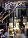
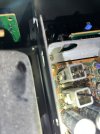
I tried to take a couple of photos with the heatsinks in situ. I took one from the front and tried to get an angle from the top. There is not much clearance, as the emitter resistors are right in the way of any potential heat sink, I think. I am not sure how I could provide a better photo with it all together. If you need another angle, let me know. I won't be removing the power pack until next weekend.

Bob
 

Attachments

  • IMG_2305.jpeg
    IMG_2305.jpeg
    118.5 KB · Views: 12
  • IMG_2304.jpeg
    IMG_2304.jpeg
    61.6 KB · Views: 12
Thanks, it's too tight for our STK-HS to fit directly. Now if you were to take out a fin or too , just maybe, but it's a PITA
 
the emitter resistors are still good?

Probably. It couldn't hurt to check them with an ohmmeter. You can do that without removing them, but general-purpose meters won't be able to measure them accurately - just look for the measured resistance to be under 1 ohm.
 
I read through https://audiokarma.org/forums/index...come-out-of-protect-plus-excessive-dc.989383/. a couple of days ago and it seems the OP experienced a similar situation to me. But given my newbie comprehension level, I was not 100 percent sure the unit's Power Pack was actually determined to be bad and the OP didn't use resistors to test the Pre-drivers after the Power Pack was removed. Instead, the Power Pack was replaced and on power up, his unit stayed in protection mode. He eventually traced the problem to the power board. Armed with new information I didn't fully comprehend, I decided to look at my power board and noticed a burnt area around TR701. I'll attach a photo, but you will have to zoom in. In person, the burnt area looks a lot darker. The power board is the only thing I ever removed in the past while trying to get access to the input selector switch. My hope is there is something wrong on the power board which emulates a blown Power Pack.

IMG_2319.jpeg

Coincidentally, and if memory serves me, the gentleman in the other thread also experienced problems with his lighting as I do. I decided to take voltage readings on the 4 lighting posts. The measurements follow.

From left to right while standing in front of the receiver:

Post 1= 29.98v
Post 2= 23.5v
Post 3= 23.5v
Post 4= -.01v

I don't know what they should be but they do not all illuminate to the same degree.

Bob
 
Last edited:
My hope is there is something wrong on the power board which emulates a blown Power Pack.

At the risk of being overly frank, I think you are grasping at straws.

The regulated power supplies serve both left and right power amp channels, so regardless of what the other thread says, power supply problems can't cause a single-channel power amp problem. I believe all evidence so far says that your receiver's regulated power supplies are functionally OK. Regulators run hot, and it's not unusual for circuit boards to be discolored in those areas.

Post 1= 29.98v
Post 2= 23.5v
Post 3= 23.5v
Post 4= -.01v

Not right, but I can't begin to speculate exactly what's wrong.

The way this is supposed to work (which is one of the quirks of this series of receivers) is that two lamps are connected in parallel to posts 1 and 2, and two lamps are connected in parallel to posts 3 and 4. All those lamps should be identical, and they should have a voltage rating of close to 14.5V. (And a current rating of around 80mA, but that's not too critical as long as all lamps are identical.) A properly working setup will have voltages on posts 2 & 3 (which are connected together) that are half of the voltage on post 1.
 
At the risk of being overly frank, I think you are grasping at straws.

Frankness is appreciated, especially as I tumble down the lengthy learning curve. No doubt, I will grasp more straws along the way.

Not right, but I can't begin to speculate exactly what's wrong.

The way this is supposed to work (which is one of the quirks of this series of receivers) is that two lamps are connected in parallel to posts 1 and 2, and two lamps are connected in parallel to posts 3 and 4. All those lamps should be identical, and they should have a voltage rating of close to 14.5V. (And a current rating of around 80mA, but that's not too critical as long as all lamps are identical.) A properly working setup will have voltages on posts 2 & 3 (which are connected together) that are half of the voltage on post 1.

Thank you for your valuable input, as knowing what the voltages should be is half the battle for me. Going forward, I plan to primarily concentrate on the lighting, as I don't want to tear it down further until a suitable donor is found. I had until now, thought the unit was untouched, but someone must have monkeyed with the lighting setup at some point in its life. Hopefully, it is a problem I can solve while I wait for a salvage,

Bob
 
Last edited:
I have had no luck thus far in finding a donor unit or power pack for the 1040. I will continue to search, but in the meantime, it has been reassembled and relocated to a closet until I can find the pack. The PA-7 should be able to step up and push the Magnepans I have been considering, but it brings with it, the most ridiculous problem I have faced in decades. And frankly I am not sure where to post my question since it has more to do with the preamp.
 
Back
Top Bottom