• Please note that Audiokarma will be offline briefly for updates early on Monday morning, September 28th.

Yamaha CR-420 Offset: - 61mV by design!

DC Offset & Measurements

ecluser:

I just did the test with R7 at 485.6 ohms. I powered up and within a few seconds I was at -.4 mv offset!! You were dead on! It then slowly moved up to around -3.7 mv. This is where it seems to stop. I told you T3 ran very warm. As I blew on it(T3) the offset came back to 0 mv and up to 1.2mv offset. When I stopped blowing on it(T3), it slowly returned to -3.7mv. You are the man!! What should I do with T3?? Put it on the heat sink?, or maybe it's own heatsink?, or the 100uf & 100 ohm paralleled between emitter and the -40 volt supply? Also, the 100k square wave that showed the spike on the trailing edge is gone now!!:scratch2:
 
Overshoots on rising or falling squarewave edges often indicate slew rate limiting. It means the amp has so much feedback that a stage is saturating in the attempt to follow that edge rate, and it takes a while to come back out of saturation after the edge has passed. This problem might simply indicate that your squarewave source should be band-limited to the audio spectrum, but it's often necessary to back off some gain and improve linearity instead. That's why I recommended adding emitter resistors in the diff amp stage earlier in this thread.
 
Square Wave Tests

Overshoots on rising or falling squarewave edges often indicate slew rate limiting. It means the amp has so much feedback that a stage is saturating in the attempt to follow that edge rate, and it takes a while to come back out of saturation after the edge has passed. This problem might simply indicate that your squarewave source should be band-limited to the audio spectrum, but it's often necessary to back off some gain and improve linearity instead. That's why I recommended adding emitter resistors in the diff amp stage earlier in this thread.

Thanks for the input! The unit had the ringing until I replaced R7 with the 485 ohm resistor. Once that was done, the square wave looked very good. You think because of the better balance between T1 and T2?:scratch2:
 
Right. Better balance probably took the stage away from a tendency to saturate more readily on one side. I would still be concerned about being so close to the limiting condition, unless you're sure that your generator produces edges much faster than what the amp will see in service. Some designers make certain by including an ultrasonic low-pass filter upstream of the amp's input stage.
 
Square Wave Test

Right. Better balance probably took the stage away from a tendency to saturate more readily on one side. I would still be concerned about being so close to the limiting condition, unless you're sure that your generator produces edges much faster than what the amp will see in service. Some designers make certain by including an ultrasonic low-pass filter upstream of the amp's input stage.

In service it should never see anything like it, I hope. You did notice that I was talking about the 100khz square wave. The 10khz has always been fine. Do you have any thoughts on T3 and the offset being sensitive to the temp of T3?:scratch2:
 
In service it should never see anything like it, I hope. You did notice that I was talking about the 100khz square wave. The 10khz has always been fine. Do you have any thoughts on T3 and the offset being sensitive to the temp of T3?:scratch2:

Most square wave sources exhibit identical rise and fall times regardless of frequency, but your ability to see the overshoot often depends on the scope's horizontal sweep rate (or sample rate).

T3 temperature is going to move around because it's dissipating a fair amount of power; about 1/3 watt. You can get better stability by sinking the heat, reducing dissipation, and degeneration. You probably need higher current gain in the output devices before you can consider reducing T3 bias current. Degeneration is attractive because it also linearizes this stage, but you could end up with less gain than you want if you're not careful. My personal preference is for local degeneration and less overall feedback. I don't like to see numerous little caps, ferrite beads, and other 'heroic' tweaks to get closed-loop stability in the face of massive gain. You could just do nothing -- a few mV of offset isn't a big deal in this context.
 
I wouldn't change anything on T3, no heat sink and no degeneration. If this transistor becomes really warm, his temperature is not likely to change with the output power since your output stage has a very high current gain.

Your final offset comes from the fact that your pair T1/T2 is not really matched. You may trim R7 or try to find a better match for T1/T2

If you choose to add degeneration on T3's emitter, please bypass the 100 uF cap by a good film cap (~0.5uF) because if you don't bypass this large capacitor, your open loop gain will drop at high frequency and this may cause you some stability issues (may need to change C3 for example). Your amp is working very well as it is, as much as I can see, don't change too much variables.

The improvement on the square wave comes from the increased current in T1 when R7 was reduced. The ultimate slew rate is limited by rate of charge of the Miller capacitor (C1) by the current from the collector of T1. So your actual slew rate is higher because the current from T1 is higher. But com'on... a 100kHz square wave in an audio amplifier... Enough is enough!

A small resistor (1k to 2k) inserted between SK2 and C2 should filter the high frequencies and you will never have ringing at very high frequency, above the audio band.
 
DC Offset and Amp Mods

Hello Guys. I can't tell you how much I thank you for your help!

Another question: I would like to tweak an old vintage amp that is 35 years old. It has a very strange looking circuit to me. Would you have any interest in looking at it?? It is push-pull but uses the same outputs for all the output transistors. Just thought I would ask.

On the other amp you have helped with, I will put the 1k in the amp board as you stated. Do you think it would help to put T3 into contact with T1 and T2? Thermally sink them together with heat sink compound. It would be easy as they are next to each other on the board. Someone else suggested that, any thoughts? :scratch2:
 
Last edited:
Puting T3 into contact with T1 and T2 will not help. The initial drifting of the offset comes from the Vbe of T3 which is reduced as the temperature of T3 becomes larger. For silicon transistors, this rate of change of Vbe is approximately -2mV/C

The only equation in cause is:

(Itail / 2) X R7 must be = to Vbe of T3

The temperature of T1 and T2 plays another role, that is maintaining the Vbe of T1 equal to the Vbe of T2. For this, T1 and T2 must be at the same temperatue but this temperature may be very different than the temperature of T3.

So, for a rise of temperature of 25 degrees C for example, the final Vbe of T3 is only 570mV and the value computed for R7, assuming a Vbe of 620mV (I neglected the temperature rise of T3 in my calculus, it's my error), is not exact. Since it is very difficult to predict the final temperature of T3, I think it is best to use a trim pot in the R7 branch and adjust the value of R7 once the temperature of T3 is stable. Without heat sink, it should be stable within minutes.

Heat sinking T3 would reduce the temperature variation but it will take more time to set at the final value, the time to heat that heat sink. At 0.3W of power dissipation, T3 can survive for many years without heat sink.
 
The temperature of T1 and T2 plays another role, that is maintaining the Vbe of T1 equal to the Vbe of T2. For this, T1 and T2 must be at the same temperatue but this temperature may be very different than the temperature of T3.

It's common in high-performance amps to thermally couple the diff-amp transistors, or even use matched transistors mounted in the same package. I don't know if good audio transistors are still available as matched pairs in a single package, but I do know that general-purpose monolithic duals are available in SMT packages because I use 'em in video circuits. DMMT3904 and DMMT3906 are the types used in current production.

I would be happy to look at another amp circuit. Please start another thread for that purpose.
 
Last edited:
Another Circuit

It's common in high-performance amps to thermally couple the diff-amp transistors, or even use matched transistors mounted in the same package. I don't know if good audio transistors are still available as matched pairs in a single package, but I do know that general-purpose monolithic duals are available in SMT packages because I use 'em in video circuits. DMMT3904 and DMMT3906 are the types used in current production.

I would be happy to look at another amp circuit. Please start another thread for that purpose.

Thanks again guys. As soon as I scan the other circuit, I will start a new thread and let you all know what it is. It would be great to find out what all is going on in this circuit. It is one of the best sounding amps I have heard!
 
My unrestored CR-420 is currently reading about 62 mv left channel, 33 mv right channel, measured after about 2 hours powered up. Anything to worry about for the time being, or should I let her alone? Still thinking I may do a full rework on this sometime in the next year or two.
 
Also, anyone know of a source for the main volume pot? Mine works, but was at some point de-ox'd to the point where the action is very "free" - i.e., no resistance when turning it.
 
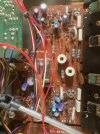
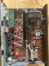
Reviving this with photos of the CR-420 receiver interior and the main power board...the blue caps all look pretty good, no leaking, Currently getting 61 mv voltage left, 5 mv right. Let alone for now? IMG_4792.jpgIMG_4791.jpg
 
Those purple ones I always suspect, if you look carefully at the legs one is typically green.
if both channels were close to each other I would leave it alone, but since one can do 5mv I would want the other to match. silly but yea.

I have some million weight silicone fluid for RC car stuff, this is very close to the goo that gives the resistance. only problem is getting it in the volume pot in the correct area. you gotta take the whole thing apart and no one wants to redo a 4gang.

Looks great on the inside super clean, have you done adjusted the bias or offset according to manual?
 
Those purple ones I always suspect, if you look carefully at the legs one is typically green.
if both channels were close to each other I would leave it alone, but since one can do 5mv I would want the other to match. silly but yea.

I have some million weight silicone fluid for RC car stuff, this is very close to the goo that gives the resistance. only problem is getting it in the volume pot in the correct area. you gotta take the whole thing apart and no one wants to redo a 4gang.

Looks great on the inside super clean, have you done adjusted the bias or offset according to manual?
Curious, where is the correct area one would apply it? Is it on the inner disc of the wiper fingers - not the finger contacts themselves.
 
Bumping an old thread but thanking the OP because I had DC offset issues and replaced the differential pair (Q303-06) with KSC1845s closely matched hFE (L -21mv, R -111; R was 50 off on the matched hFE!) and that brought each channel to -51. 620 ohm resistors, replacing 1.2K at R407-08 brought offset ~10mv each channel. @ecluser's math is exact.
 
Back
Top Bottom