I did not discharge them but the receiver has been off for about 2 days and they are small ceramic caps, but yes even if I set my MM to 2M ohms both C703 and C704 just read 0L immediatelyIf you measure the resistance of a capacitor and it measures OL right from the beginning it is open. It sounds like you are saying C703 and C704 are open? Did you discharge them first?


You are using an out of date browser. It may not display this or other websites correctly.
You should upgrade or use an alternative browser.
You should upgrade or use an alternative browser.
Yamaha CR-600 restoration advice
- Thread starter Joolian
- Start date
Sorry, reverse the probes for measuring which components?Plz repeat the measurement then repeat but reverse the probe orientation.
Appears you are measuring path R713, D702, D701,R714, F801...
Was this measurement done with F801,,, removed?
I currently have all four power supply fuses removed.
Resistance to GND??? try measuring from R713(either side)Sorry, reverse the probes for measuring which components?
Bottom of R713 is giving me 5.6k ohms, top is giving me 4k ohmsResistance to GND??? try measuring from R713(either side)
4.7k at bottom of R714, 3.7k at top
Both D701 and D702 show about 4k ohms on their outer ends and 0 ohms towards the middle
Same readings on everything with probes reversed

@Joolian it might make sense to step back and summarize were you are at as this has taken some twists and turns.
- Power supply was in question but it was just something further downstream making the receiver only drawing 62V on a 100W DBT
- The bias on both channels was wrong and could not be adjusted
- The fuses for the left channel power rail were blown
- The collectors of output transistors on the left channel were measuring 1KΩ to ground (OL on right channel)
- The left channel output transistors were reversed
- 13kΩ from emitter of left channel TR705 to ground. On right channel (TR706) it is OL
I am not sure what was tested with fuses in vs out, what was compared to the right channel, and if the receiver has been back on the DBT since the left channel output transistors were flipped. While you have been concentrating on the left channel the bias on the right channel was 0V and not adjustable...
- Power supply was in question but it was just something further downstream making the receiver only drawing 62V on a 100W DBT
- The bias on both channels was wrong and could not be adjusted
- The fuses for the left channel power rail were blown
- The collectors of output transistors on the left channel were measuring 1KΩ to ground (OL on right channel)
- The left channel output transistors were reversed
- 13kΩ from emitter of left channel TR705 to ground. On right channel (TR706) it is OL
I am not sure what was tested with fuses in vs out, what was compared to the right channel, and if the receiver has been back on the DBT since the left channel output transistors were flipped. While you have been concentrating on the left channel the bias on the right channel was 0V and not adjustable...
I’ve had the fuses out since the left channel ones blew, and I haven’t turned the unit on since flipping the outputs (probably a good idea as I don’t think I actually had them reversed, the schematic shows the NPN and PNP inverse on the left channel from the right channel, but the board labels it as both NPNs up top and both PNPs on the bottom (I think the board is correct and that’s how I originally had them). But yes power supply is fine. I’ve compared every component I can to the right side to try and find anything that sticks out but unfortunately there’s nothing to compare the section of the circuit with D701/D702 to. However, even though that section is mostly involved with the left channel, it does connect to both VR701 and VR702, so I do wonder if whatever’s causing the grounding issue on the left channel is also causing the pots to freeze up@Joolian it might make sense to step back and summarize were you are at as this has taken some twists and turns.
- Power supply was in question but it was just something further downstream making the receiver only drawing 62V on a 100W DBT
- The bias on both channels was wrong and could not be adjusted
- The fuses for the left channel power rail were blown
- The collectors of output transistors on the left channel were measuring 1KΩ to ground (OL on right channel)
- The left channel output transistors were reversed
- 13kΩ from emitter of left channel TR705 to ground. On right channel (TR706) it is OL
I am not sure what was tested with fuses in vs out, what was compared to the right channel, and if the receiver has been back on the DBT since the left channel output transistors were flipped. While you have been concentrating on the left channel the bias on the right channel was 0V and not adjustable...
My CR600 main amp board is currently apart and I am waiting for caps. However the attached photo was taken from my working unit before I removed the output transistors. So hopefully that clears that up for you. Since you suspect D701 / D702 have you tested them?
Attachments
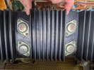
Thank you for that! So I did have them in correctly to begin with. Other than that voltage test a few days ago on the two zeners (which looked ok), I haven’t checked anything more with them. I suspected the ground for the short was coming off the ground terminal at the top of the board, but that only has two traces coming off of it and they are both fine.My CR600 main amp board is currently apart and I am waiting for caps. However the attached photo was taken from my working unit before I removed the output transistors. So hopefully that clears that up for you. Since you suspect D701 / D702 have you tested them?
EDIT:
Looking back at the bottom ground trace, it only has two places to go: TP5, and R749. C723 was already tested and was fine, so the only other component coming straight off the other end of R749 is C725 (which I can’t find listed on the actual schematic, only on the “drawing” of the board). This cap is C726 on the right channel. On the right channel, resistance on the leg towards the middle of the board climbs up to infinity no problem. The inner leg on the left channel maxes out at about 60k ohms. Maybe my issue, or could its resistance be getting brought down by a short somewhere else?
Last edited:
This means that you don't know why the fuses for the left rail blew.Thank you for that! So I did have them in correctly to begin with.
If the left channel is shorted to ground, would the fuses have blown when I took it off the DBT?This means that you don't know why the fuses for the left rail blew.
I just had a look at the beginning of this thread. When you got this receiver the fuses were good and you were able to adjust the right channel. The left channel was at rail voltage and had no bias. Because of this the protection relay was not clicking. I am fairly new to this hobby but my understanding is the usual approach is to find out what is wrong with the problem channel before recapping.
It seems you used JD Audio's part list and redid the power supply and power amp boards. Is that correct? When this was done you posted "I went in and set the idling current on both channels no problem, however when I went to set the mid-point voltage it was sitting around 6V on both channels.". You then discovered that you had the pinout wrong for TR705 and TR706 on the power amp board and had some transistors in the protection circuit where not in correctly.
It is weird that you were not blowing fuses are were able to set the bias on both channel after the rebuild and now neither of those is true. My only suggestion at this point is to double check the orientation of all transistors and capacitors on the power amp board. It is worth reading the JD Audio thread closely as dead_SHORT had some specific issues with transistor pinouts. Also if you don't have one a $20 GM328 tester is very helpful for confirming transistor pinouts.
JD Audio CR600 thread.
It seems you used JD Audio's part list and redid the power supply and power amp boards. Is that correct? When this was done you posted "I went in and set the idling current on both channels no problem, however when I went to set the mid-point voltage it was sitting around 6V on both channels.". You then discovered that you had the pinout wrong for TR705 and TR706 on the power amp board and had some transistors in the protection circuit where not in correctly.
It is weird that you were not blowing fuses are were able to set the bias on both channel after the rebuild and now neither of those is true. My only suggestion at this point is to double check the orientation of all transistors and capacitors on the power amp board. It is worth reading the JD Audio thread closely as dead_SHORT had some specific issues with transistor pinouts. Also if you don't have one a $20 GM328 tester is very helpful for confirming transistor pinouts.
JD Audio CR600 thread.
You’re completely right, I went into this one with false confidence after having successfully finished my first recap on a turntable and kind of went for a shotgun approach with replacing a bunch of components before actually solving the issue fundamentally. I have checked all transistors on main amp, TR707 and TR708 I had backwards and have now corrected. I did have TR705 and TR706 in incorrectly, although after checking that JD Audio thread TR705 is STILL wrong (I went off the schematic but according to others’ units both transistors face the same way). Trying to get that back out again to flip it around and then we’ll see how things look.I just had a look at the beginning of this thread. When you got this receiver the fuses were good and you were able to adjust the right channel. The left channel was at rail voltage and had no bias. Because of this the protection relay was not clicking. I am fairly new to this hobby but my understanding is the usual approach is to find out what is wrong with the problem channel before recapping.
It seems you used JD Audio's part list and redid the power supply and power amp boards. Is that correct? When this was done you posted "I went in and set the idling current on both channels no problem, however when I went to set the mid-point voltage it was sitting around 6V on both channels.". You then discovered that you had the pinout wrong for TR705 and TR706 on the power amp board and had some transistors in the protection circuit where not in correctly.
It is weird that you were not blowing fuses are were able to set the bias on both channel after the rebuild and now neither of those is true. My only suggestion at this point is to double check the orientation of all transistors and capacitors on the power amp board. It is worth reading the JD Audio thread closely as dead_SHORT had some specific issues with transistor pinouts. Also if you don't have one a $20 GM328 tester is very helpful for confirming transistor pinouts.
JD Audio CR600 thread.
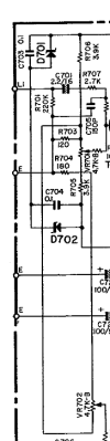
Hello, it's me again. I imagine everyone's sick of this thread by now but I have pinpointed the ground short to the top of the board just under VR701 and VR702. The ground source on the left channel side of the board comes into the top center of the board, off of which comes D701/D702, C703/C704, and R703/R704. I imagine this area of the board is for decoupling though I'm unsure. Regardless, when I remove both R703 and R704, the ground short is gone. This to me says that the zeners and caps underneath those two resistors are doing their job properly, however I don't know where you're supposed to "lose" the ground in this circuit. There are two vertical resistors (I had to draw one in on the PCB drawing as they aren't labelled well there, but on the schematic I believe these to be R705 and R706, and those two resistors on the schematic and the board itself are 3.9k) which are carrying the ground from R703 and R704 down towards my left channel output collectors. Does anyone who understands circuits know how this is actually supposed to work? Are VR701 and VR702 supposed to prevent the ground from reaching +BL?

Last edited:
Need a bit of time to go through the history....Regardless, when I remove both R703 and R704, the ground short is gone.
One observation, yamaha use odd part numbers for left channel and even for the right. If problem is only affecting one channel then try removing only the applicable resistor (R703=Left, R704=Right)

Sparkplug
Super Member
When you remove R703 and R704, you’re essentially interfering with the operation of VR701 and VR702 that adjust the bias on the differential pair transistors, TR701, 703 and Tr702, 704 that set the DC offset voltage among other things. This is not a solution.… when I remove both R703 and R704 …
If a short is what you’re worried about, clear out the area of the board you’ve highlighted (after taking photos), clean the board thoroughly, test the components out of circuit, and put them back in. Then test again. I haven’t looked at this in any detail but have a feeling the issue is probably somewhere else.

Also what @mbz stated above. It’s very unlikely that you’d have a short on both channels although I see in this circuit there are some shared lines which affect both channels.
Heading out the door, need to get some parts.

Oh I know that pulling them isn't a fix, but it's at least somewhat telling me where the short is coming from. I had initially pulled R703, no change, so I pulled R704 and short was gone - put R703 back in, short was back. It's difficult (for me, at least) because the circuitry is so different on the left and right channels that even though I don't have the same issue on the right channel, there's really nothing to compare to. Since everything else in the area tests fine I suppose it would be an issue with VR701 and 702. I was thinking before that the ground short was causing my issues with them, but now I think it's the other way around. I've pulled the diff pairs before and they tested fine but I will go through the area again tomorrow.When you remove R703 and R704, you’re essentially interfering with the operation of VR701 and VR702 that adjust the bias on the differential pair transistors, TR701, 703 and Tr702, 704 that set the DC offset voltage among other things. This is not a solution.
If a short is what you’re worried about, clear out the area of the board you’ve highlighted (after taking photos), clean the board thoroughly, test the components out of circuit, and put them back in. Then test again. I haven’t looked at this in any detail but have a feeling the issue is probably somewhere else.
Also what @mbz stated above. It’s very unlikely that you’d have a short on both channels although I see in this circuit there are some shared lines which affect both channels.
Heading out the door, need to get some parts.
Sparkplug
Super Member
Seems you’re approaching this methodically which is nice to see. I’d change those trimmer pots with new ones and test again. May very well solve your problem.Oh I know that pulling them isn't a fix, but it's at least somewhat telling me where the short is coming from. I had initially pulled R703, no change, so I pulled R704 and short was gone - put R703 back in, short was back. It's difficult (for me, at least) because the circuitry is so different on the left and right channels that even though I don't have the same issue on the right channel, there's really nothing to compare to. Since everything else in the area tests fine I suppose it would be an issue with VR701 and 702. I was thinking before that the ground short was causing my issues with them, but now I think it's the other way around. I've pulled the diff pairs before and they tested fine but I will go through the area again tomorrow.

Edit: Have you tested the Zener diodes D701, 702? You could at least check the voltage drop across them to see if they’re functioning. I don’t know what their voltage ratings are.
Last edited:
I have tested them prior and they were okay. Trim pots are new, I have them out right now and they function fine. Because their voltage was stuck when they were in, I thought that the ground short was causing that. If it's possible that it's the other way around (that the locked voltage is causing them to leak ground through to my left rail), I'm going to throw them back in and work backwards from the wipers. Unfortunately there's not many voltages to go off in that area of the schematic.Seems you’re approaching this methodically which is nice to see. I’d change those trimmer pots with new ones and test again. May very well solve your problem.
Edit: Have you tested the Zener diodes D701, 702? You could at least check the voltage drop across them to see if they’re functioning. I don’t know what their voltage ratings are.
Sparkplug
Super Member
How did you test them? Please advise.I have tested them prior and they were okay.
Unfortunately there's not many voltages to go off in that area of the schematic.
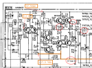
You can roughly calculate them if you know the bias currents for the Zeners. Also, it seems the schematic doesn’t show grounding for some elements (Zeners and a couple of caps), I added it in with an oversized dot below on the left. Without it, things don’t make sense. Another strange thing I noticed is that the rail voltage for the differential pairs of both channels is provided by +BL line! Why I am not sure, why isn’t BR used for the right channel? Need to check the PCB Layout. But I digress … please Ignore other marks, they’re from a different problem.